![]()
| I mentioned at the end of the last page that the first thing to do on
the FuryRacer over the winter break was to write down a list of the things I wanted to do. And here it is: 1. Refit oil takeoff plate, refit remote oil filter head, and fit oil cooler. 2. Cut away returns around the front wheel arches and respray edges. 3. Repair and reinforce bonnet mounting points on side pods. 4. Fit new aerocatches to the top of the bonnet and fit bonnet pins to the scuttle. 5. Make a new foam seat and cover it with Nomex fabric. 6. Machine a new billet sump and fit it. 7. Sort out fuel gauge problems. 8. Establish the proper calibration for fuel gauge. 9. Modify the headrest and relocate the harnesses to the chassis mounts. 10. Check relocated harnesses for compatibility with a HANS device. 11. Sort out the yaw gauge 12. Make new airbox with feed from NACA duct in nose and panel filter in airbox Contrary to the impression given by the silence over the last few months, I have been getting on with these albeit rather slowly. |
| The most pressing thing to sort out was the oil system and in particular to try and sort out the oil cooling. The obvious solution is of course to fit an oil cooler, but this requires some way of getting the oil from and to the engine via the oil cooler. And the obvious solution to the absence of any built-in oil cooler ports was to use the take-off plate I'd made earlier to allow me to fit a remote oil filter. However, I'd already removed the take-off plate because it suffered from two main problems. The first was that the two JIC fittings were too close together and as a result it was very difficult/impossible to fit the hoses to it and get them to seal properly. The second was that unfortunately when I'd tapped the M20x1.5 thread down the middle of the take-off plate, I hadn't done it straight - as a result the take-off plate didn't sit flush and leaked slightly even when tightened up as hard as I could get it. |
| So it was time to make a new one. The process was essentially the same as when I made one the first time around, but with a few differences. Firstly, I spaced out the JIC fittings a little so that the hoses would be easier/possible to fit properly. The other change was to allow the take-off plate to be fitted more easily. There isn't much room around the take-off plate or oil filter - there's lots of hoses, pipes and engine mounts in the way which means it's certainly impossible to get your hand around the take-off plate. So, in order to help get it on and (to a lesser extent) off, I've machine some little slots in the side of the take-off plate. |
| I did this using a rather Heath Robinson arrangement of a rotary table mounted on its side, an MT2-J0 taper, a drill chuck, and the M10x1.5 tap I'd used the make the thread up the middle of the take-off plate. | 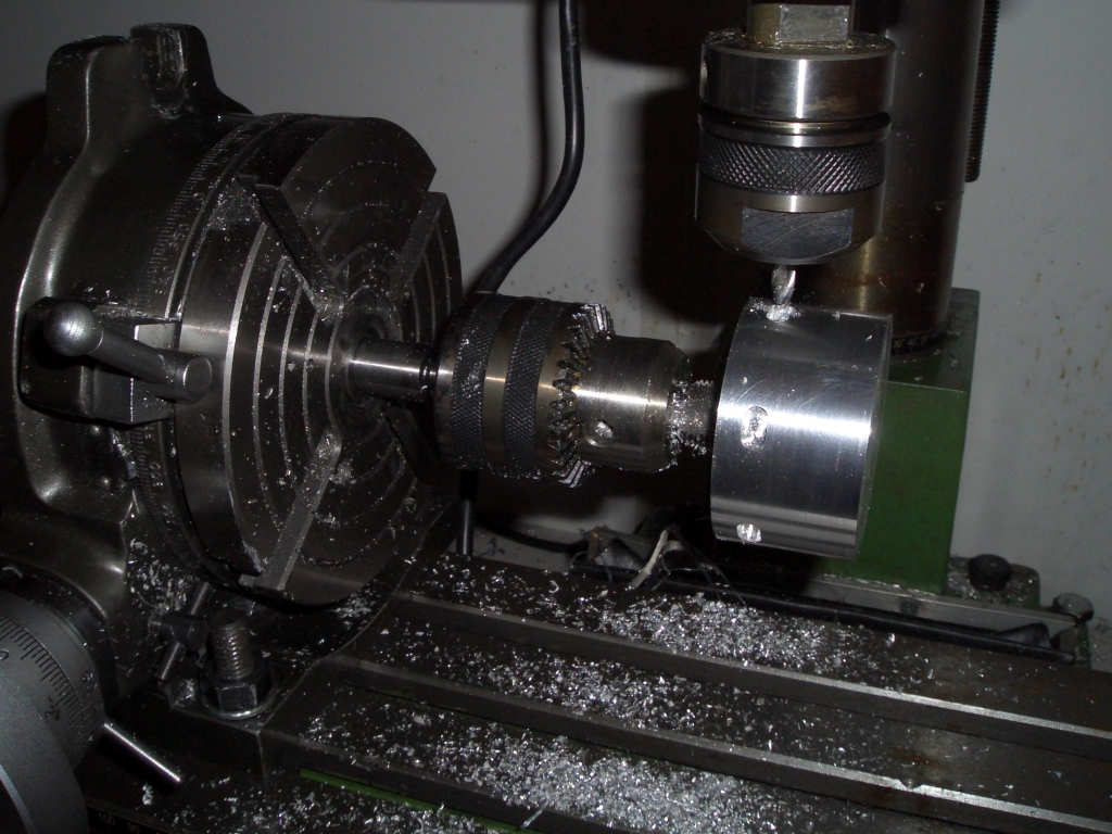 |
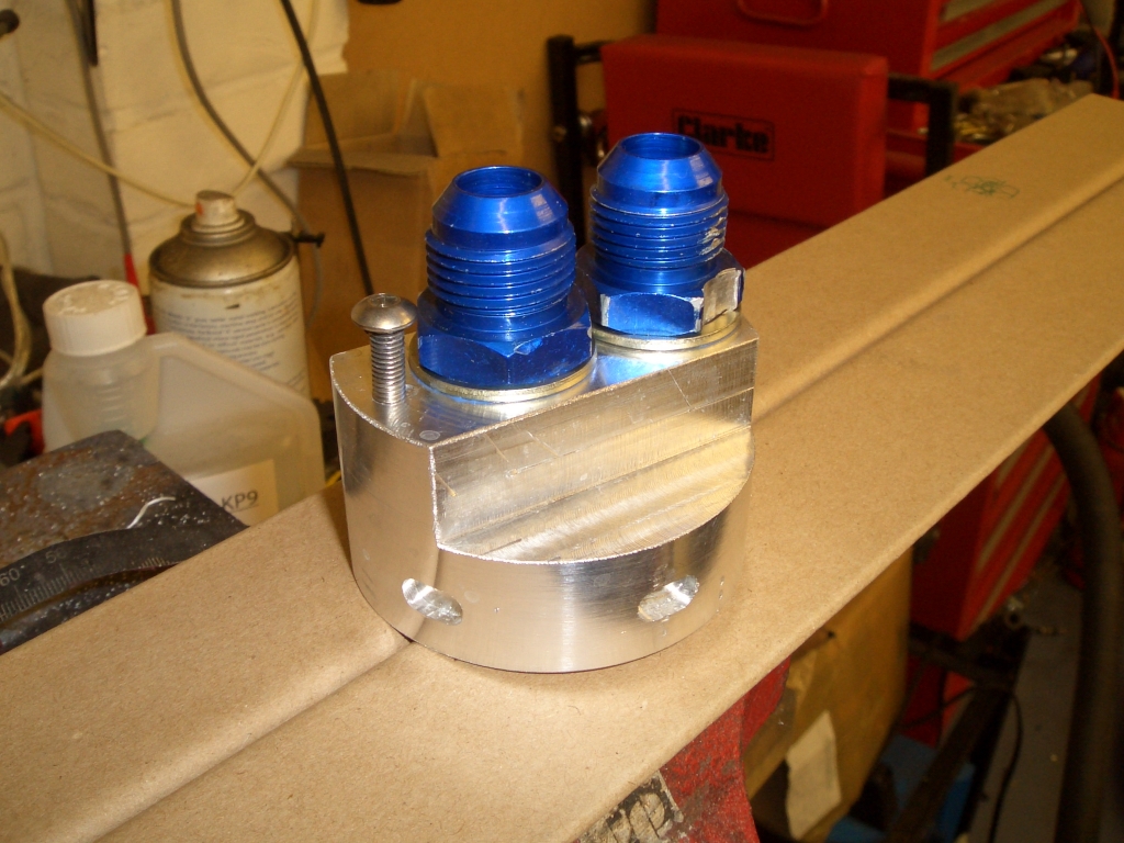 |
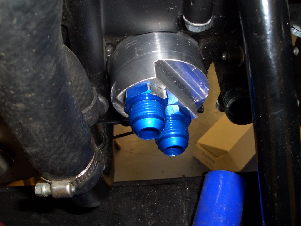
With the JIC fittings in place (with some bonded rubber sealing washers) and a short bolt to wrap a zip-tie around to make sure it doesn't undo itself in use, the take-off plate looks like this. The point of the little slots around the circumference it so that I can use a (rather extensively modified) C-spanner to tighten up the take-off plate when fitting it. So the oil system now starts off with... |
| ...the new take-off plate, sitting where the oil filter would normally be, with the oil hoses attached to it, going off to... | 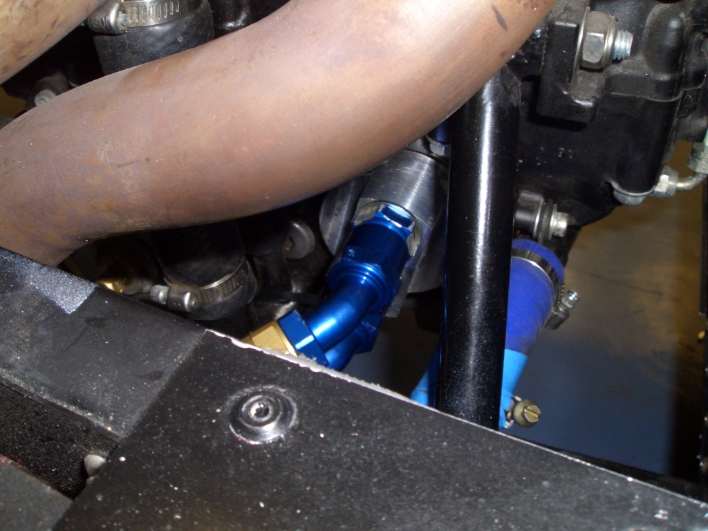 |
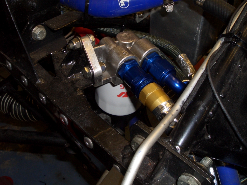 |
...the reinstated remote oil filter, and then off to... |
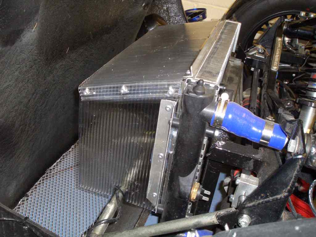
| ...the new oil cooler fitted right in front of the water radiator. It then heads back (via a hose just over 5 feet long) back to the engine. If nothing else, the new oil system should add nearly a litre to the fluid capacity of the oil system. The only job left to do here is to modify the radiator duct I made earlier to allow the oil hoses to go through it, and to refit that. Mind you, since I've pre-filled the oil cooler with oil, and given that in order to refit the shroud I have to take out the bolts holding it in place, that could be easier said than done. | 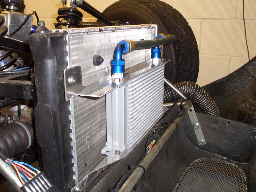 |
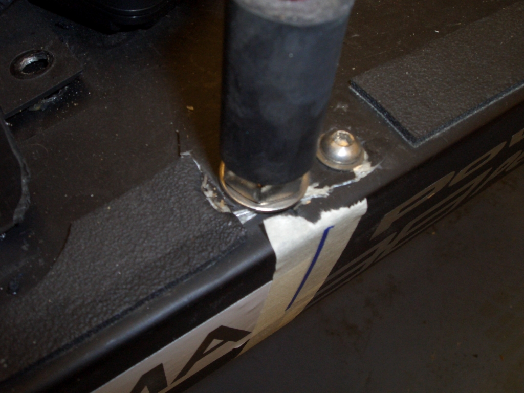 |
The problem here was simple. I'd mounted the bonnet pins onto which the bonnet's Aerocatches attach on two small aluminium plates in the sidepod. Unfortunately, the small size of the aluminium plates, the thinness of the GRP in the sidepods, the heat from the engine and the lifting forces from the bonnet all conspired to start pulling the aluminium plates through the sidepods. |
| So I made up a couple of rather beefier mounting plates from 16g mild steel with an M10 nut welded to them and fitted them inside the sidepods by bonding them into place with a couple of layers of CSM. The holes in the mild steel plate are so that the new GRP being laid up to hold the plate in place can get cosy with the existing GRP of the sidepod and help hold the mounting plate firmly in place. The pins for the Aerocatches are now much more rigid and there's no way that the newly reinforced mounting plates are going to pull through. | 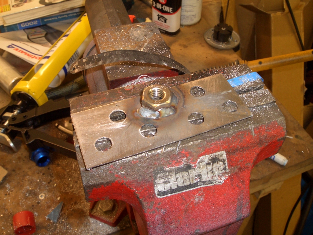 |
 |
While the exhaust (passenger) side sidepod was off the car I took the
opportunity to cut some more holes in the underneath of the sidepod to help keep the exhaust system cool, and in
particular around the catalytic converter. During testing at Snett I'd make a somewhat hurried and unscheduled
stop in the pits without a cooling-down lap, and from the gases being emitted from the sidepod it was clear it
had got rather toasty. I also discovered that the heat-resistant mat I'd bonded into place was delaminating and
falling apart and that the aluminium foil I'd put in alongside it was falling off too. I've never been that convinced of the wisdom of putting a highly conductive layer of material alongside the GRP you're trying to keep cool, so rather than replace the aluminium foil and heat resistant mat I've sprayed the inside of the exhaust sidepod with chrome paint. It's surprisingly shiney for a 1k paint and hopefully will reflect a reasonable amount of the radiated heat coming off the exhaust system. I've also cut a geet big 'ole in the sidepod underneath the cat, to try and reduce the amount of GRP nestling up against it and also to increase the potential for air-flow across it. If this and the shiney shiney paint doesn't work then I'll see how much Zircotec are asking for their new ceramic/aluminium heatshield cloth. |
| Not that I'm slavishly following the crowd, or anything, but these days
everyone who's anyone has an in-car video recording system when they go racing. So I'm going to have one too. Actually,
this has been on the cards for a while now, hence the fact that I've had most of the necessary kit sitting in the
garage for about 2 years now. Of course there's a wide range of in-car video systems on the market. There's Race Technology's Video4 system, which while apparently very competent costs nearly a grand. There's the Goldstar systems, which aren't exactly cheap. At the other end of the scale there are a huge number of seemingly identical solid-state recorders on eBay at ludicrously low prices with rather less modest shipping costs from various locations surrounding the South China Sea. Faced with such a bewildering range of options, there's only one thing to do. Copy Tim, as usual... In practical terms this means using a bullet-cam and a Neuros II mpeg 4 recorder. The Neuros is a nifty bit of kit which takes a standard AV signal and records it onto a CF card in (surprise, surprise) mpeg4 format. There are a few downsides to it - it's not waterproof, it needs a 5V power supply (the mains adaptor supplied with it is rather less than useful unless your racecar has a 240V AC power supply), and it has no buttons - you have to use the remote control it ships with to turn it on and off. None of these are insurmountable, of course, but it seemed sensible to start off with the power supply. |
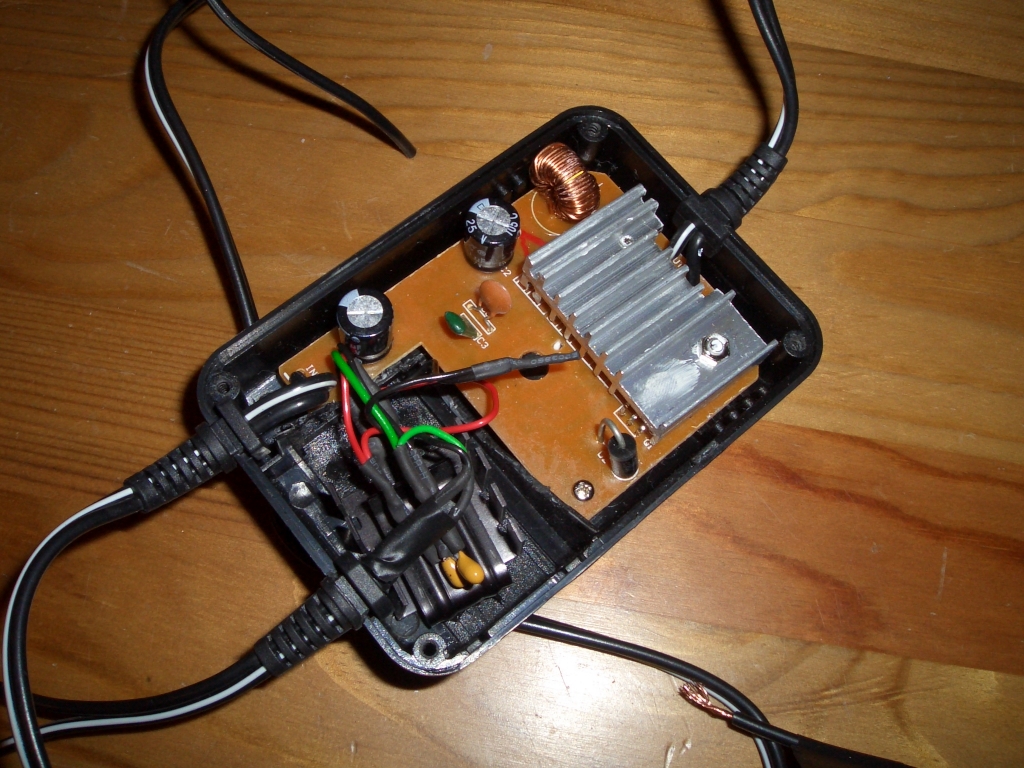
| The power supply needs to supply a 5V supply to the Neuros but also
a 12V supply to the bullet camera. And as any fule kno, while cars' and bikes' electrical circuits are nominally
12V, they actually run at about 14V. Now it may well be that the un-named un-branded bullet camera I got off eBay
will be perfectly happy with having a wildly fluctuating power supply veering from 11V to 15.5V stuffed up it,
but I suspect the odds are against it. So I need a power supply which can be connected to the car's electrical
system and provide me with 12V and 5V. There are various ways to achieve this. Tim's method is to use a couple of simple linear voltage regulators, and this method has a great deal to commend it. It's cheap, easy to do, and evidently works. On the other hand, while using a linear regulator to get a 12V supply is perfectly sensible (and, indeed, is precisely what I've done), using one to go from 14V to 5V has certain undesirable features. This is due to the way in which linear regulators work. This is, I must admit, not an area in which I can claim any particular expertise (actually, any at all) but essentially a linear regulator works by dumping the excess voltage as heat. That means that a regulator supplying 1.2 amps at 5V from a 14V supply (and the Neuros mains PSU is rated at 1.2 amps) is dumping about 10 watts of heat when it's working. That in turn means the linear regulator needs to be attached to a fairly large heatsink in order for it not to promptly fry itself, which can be easily achieved by mounting the regulator on part of the internal panelling of the car, but also means that you're wasting quite a chunk of the alternator's output heating the car's chassis up. Anyway, I was eventually persuaded by Steve that a more, well, elegant solution was to use an off-the-shelf switched-mode power supply to provide 5V and to bodge a linear regulator into the casing to do the 12V supply. So I bought the wee box he recommended, once again from eBay, only to find that it didn't actually have a 5V output. 4.5V, no probs. 6V, easy. But not 5V. To be honest 4.5V would almost certainly have been fine, but in the end I worked out what needed to be changed in the wee box to get it to produce 5V, and left Steve to do some SMT resistor unsoldering and resoldering magic. Which he was able to do very easily, once he'd remembered to turn the soldering iron on... The space in the bottom right hand corner of the box is designed to take a small key-like thing to turn the recess knob which sets the voltage output. Said knob doesn't now do anything, since the switch has been made redundant by a bridging a couple of tracks on the circuit board so it's fixed to 5V. However, the space for the key is the perfect size for a 12V linear regulator, a heatsink, and a couple of tantalum smoothing capacitors. The cable with the strain relief grommet which I've used to connect it to the outside world originally lived on the ciggy lighter attachment on the end of the power supply's supply cable. I've tested it, and it seems to work fine. The 5V is actually a wee bit more than 5V, and perhaps unsurprisingly the 12V linear regulator doesn't quite produce 12V when the engine's not running (can't run the engine at the moment since it has no oil in it), but given that it's not even a low drop-out regulator it seems to deal with it pretty well. Next up is putting the Neuros in a waterproof enclosure (i.e. Tupperwaresque box), mounting the camera, and wiring it all up. |
 |
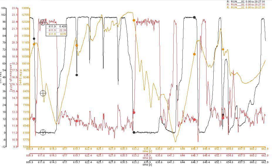
| One of the things I spotted looking at the data traces from Snetterton was that
the air to fuel mixture was running rather rich at WOT on the Revett Straight. Rather than running at between 12.5
and 13:1, which is what I'd expect, the engine was running at between 11.5 and 12: 1. Although the car was running
with its Dynajet Power Commander piggy-back ECU at the time, the only part of the map I'd modified from standard
was between idle and 3.5krpm, in order to get it through the SVA test - the rest of the map was standard. Now it
may be that Mr. Yamaha considers that 11.5 to 12:1 is the proper AFR for his engines to be running at on WOT, but
I think that's unlikely frankly. A more logical explanation to me seems to be that there's something strangling the engine. It could be the exhaust, which as I've already said is a bit experimental in its lengths and configuration. However, I suspect that a more likely candidate is the airbox and induction pipework. The air filter is rated for 300bhp+, so I don't think that's the problem, and while it's stuck away in the sidepod there should be plenty of free air around it - the sidepod's not sealed in any way. However, the air filter is linked to the remains of the airbox by a rather long length of 80mm ducting, and I suspect that this is causing the problem as it does have to take a rather tortuous course over the steering column and into the modified airbox. Also, while it would be possible to duct cool air into the sidepod so the existing airfilter is getting a nice cool supply of air, it adds unnecessary additional complexity. The easiest thing to do would be to have a duct at the front of the car taking air to a sealed airbox incorporating a panel filter. A bit like the AB Performance set-up that Tim, Uncle Tom Cobbley, and all, uses on their cars then... Now if I was running a Honda engine I could go to Andy Bates and get a complete system, but that's not possible with the R1 engine. So while I can get the NACA duct to go in the bonnet from Andy, I'll have to make my own airbox. The airbox will largely replicate the shape of the existing airbox - it has to really, given that most of it's quite tight up against the inside of the bonnet bulge'o'doom - but will be split along the horizontal plane and will have a panel filter sitting between the two halves of the airbox. Given the width of the airbox, and the maximum depth I have available, it looks like a panel filter from a Peugeot 106 GTi is going to be the best bet. I've compared the dimensions of one to the air filter from the R1 airbox, and it looks like the 106 GTi air filter has a greater surface area, so at least it'll be no worse than the standard bike airbox in that respect. |
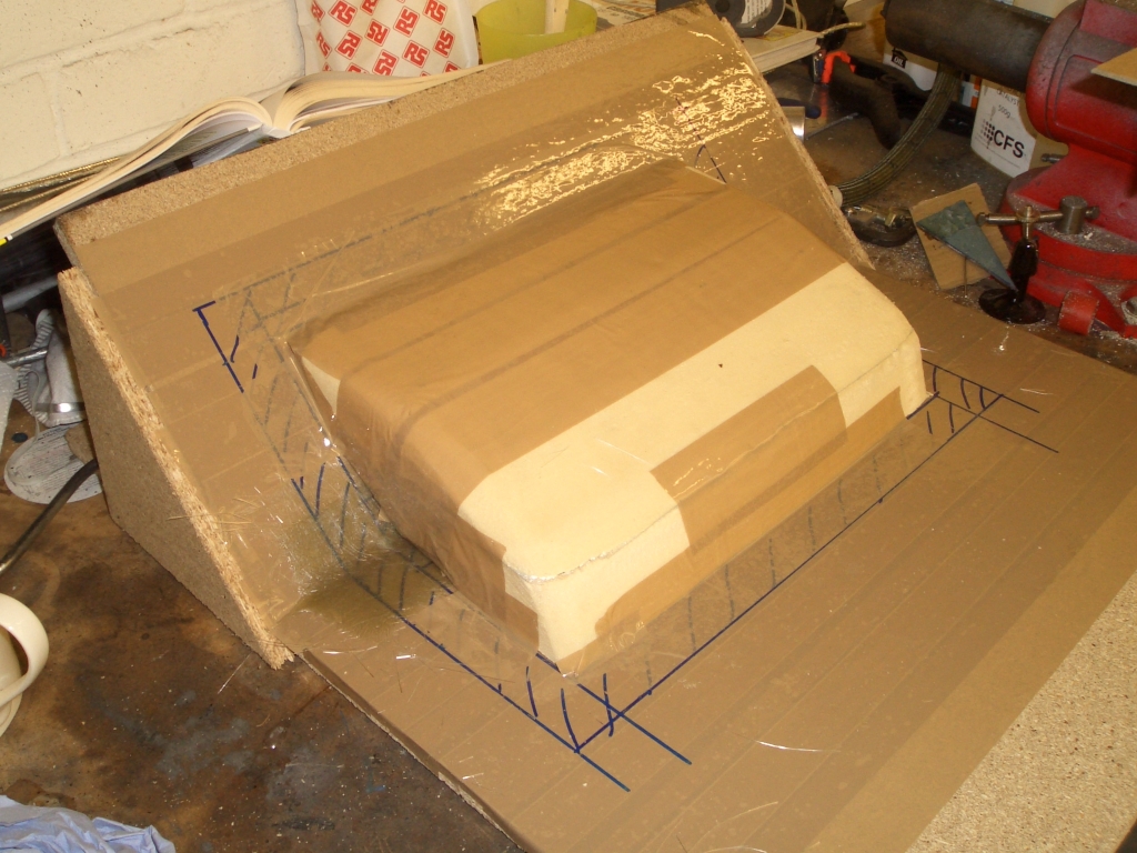 |
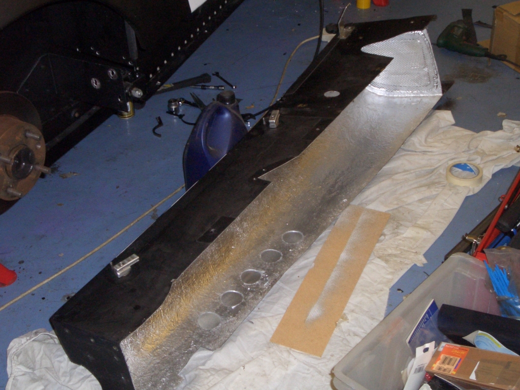
This picture shows the 'mould' in progress. The mounting face for the
airfilter is at 45 degrees from horizontal, so the chipboard base replicates this. I moulded the shape of the
airbox itself from polyurethane foam (actually bits of 40mm Kingspan insulation I had left from insulating the
garage doors), and once it's roughly in the correct shape I covered the resulting shape in packing tape, my favourite
quick-to-apply release agent. If you look carefully you can see a bit of CSM already in place on the mould. Basically I needed the airbox to be a box, as the name suggests, with two holes in it - one hole on the face of the airbox next to the angled bit of chipboard, to go from the airbox into the throttle bodies, and one on the horizontal bit of chipboard to fit the air filter into. |
| Then three layers of 220gm/m CSM over the top, with polyester resing. Probably an excessive quantity of GRP, but it's not exactly a big thing so weight isn't much of an issue, and while it doesn't need to be particularly strong (it's not going to be under significant pressure or vacuum - if it works properly) I'd rather not have it fall apart. |  |
 |
After the polyester resin can cured, I just had to pop the airbox away
from the packing tape on the chipboard base, hack out the polyurethane foam with my trusty garage bread knife,
and remove the packing tape from the inside of the airbox. And here it is, untrimmed and fresh from the now-destroyed
mould. The edges need to be tidied up, obviously, and there are a couple of spots on the mating faces which need
to be filled with a touch of flow coat because the packing tape was wrinkled - the airbox is supposed to be essentially
air-tight after all. The next steps in the airbox manufacturing process are to fit the NACA duct in the bonnet, to buy a panel filter, and to make up the lower half of the airbox which will connect the NACA duct to this bit of the airbox. |