14th October 2007

Exhaust - tail pipe

  With the exhaust on the FuryRacer, as usual, I'm trying to cram in a great deal into not much room. I want to have a 4-2-1 manifold, there's got to be room for a cat for the SVA test, and a full length exhaust can. That means that space is at something of a premium.

The tail pipe which I had fitted on the exhaust can off the Furybird I was a 45 degree tail pipe, and had a fairly generous sliding fit section onto the can. The net result was that it was a good few inches longer than it needed to be.

The new 90 degree tailpipe (just a 90 degree 2 inch diameter S/S bend I got off eBay) needs to have a rolled end for SVA purposes, so I just cut the end off the old 45 degree tail pipe and TIGed it onto the 90 degree bend.

Then, having chopped everything down as much as I reasonably could, I welded the 90 degree bend onto the exhaust can. Again, this is the old unit which I had fitted to the Furybird I.

I also welded onto the can a little stainless steel tab to use for mounting it onto the chassis. The bracket's just two 16g stainless L-shaped tabs, welded back to back and then onto the exhaust can.
 

  The exhaust can along with the cat's mounted rigidly - like on the Furybird II I've decided to go for the (fairly) rigid mounting option on the basis that the engine is rigid mounted so there's no reason why the exhaust mounts shouldn't be fairly rigid as well. The mount from the chassis is just a short length of steel with a gusset and a bit of 3mm plate welded on the end.

You can see the catalytic converter in the picture too. I got this off, once again, eBay for the bargain sum of 17 quid - not bad for a new cat, even if it is a ceramic one. The end of the cat wasn't quite the right size - it was the same size as the end of the exhaust can rather than being slightly smaller so that it would fit inside the slip fitting. But I had some stainless tubing of the correct diameter, so I chopped one end of the cat and welded a short length of new stainless tubing in its place.

Oil filter take-off plate

The oil filter on the 2006 R1 engine is in the usual place - at the front of the engine (as it's installed in the bike) underneath the exhaust manifold. Fine for access if it's in a bike - but in a car, it's a pain - it's buried inside the chassis, it's got one water pipe on one side, it's got a water hose on the other curling round over the end, and it's wedged up against the chassis rails hiding underneath the exhaust. I reckoned that even if I panelled the nearside of the engine bay (as I intend to do), I could still

The oil filter on the 2006 R1 engine is in the usual place - at the front of the engine (as it's installed in the bike) underneath the exhaust manifold. Fine for access if it's in a bike - but in a car, it's a pain - it's buried inside the chassis, it's got one water pipe on one side, it's got a water hose on the other curling round over the end, and it's wedged up against the chassis rails hiding underneath the exhaust. I reckoned that even if I panelled the nearside of the engine bay (as I intend to do), I could still just about change the oil filter. However, it would involve getting to it from underneath the car and would be a really really upleasant job.

So I bought the take-off plate on the right, with the correct M20 x 1.5 thread for the R1 engine, so that I could relocate the oil filter to somewhere where it'd be more accessible. But the take-off plate doesn't fit - it's too wide to fit next to the water pipe which runs along side the oil filter.
 

  A sensible person would of course look around for an off-the-shelf alternative which fitted, and if that wasn't possible, just resign themselves to some pretty unpleasant filter changes in the future. I did the first of these, but couldn't find anything. However, I did find a nice lump of round ali bar which at 3 inches diameter was just a little larger than the 68mm space that the oil filter take-off plate had to live in...

So I decided to make my own. Looking at the Mocal unit I decided that if I was a little bit more aggressive about the spacing between the 1/2" BSP ports on the top of the take-off plate it should be possible to reduce the overall width of the unit to a maximum of 68mm and still have a reasonably smooth and unobstructed flow for the oil through the plate.

On the left is the lump of ali, faced off and with half of it turned down to 68mm. I'm in the process of machining the 24mm deep 19mm wide hole down the middle of the take-off plate which will be threaded to M20x1.5 to allow it to mount onto the engine. I machined this central hole using my boring head (ho ho ho), a very useful tool I'd forgotten I'd got...

Some further machining was required on this face of the workpiece for the slot which the sealing ring fits into and for the slot round the outside of the adaptor. The sealant ring is off a spare Champion F306 filter I had in the garage - obviously I didn't keep it in place while doing the machining, this is just a trial fit.

It was quite hard machining the outer slot for the oil flow - the underside of whatever tool I used kept on hitting the outside of the unmachined part of the workpiece. In the end I just resorted to taking some (relatively) cheap braized carbide tooling and griding away the underside of the end of the tool (where the carbide cutting bit is brazed to the body of the tool) in order to increase the clearance. I wasn't sure if this was a good idea but Dave Turner, cam7's resident machining guru said it was fine. Anyway, it's all done now.


  With all the machining on the face closest to the engine done (or at least, as much of it as I could do on the lathe), I took the adaptor out of the 3 jaw chuck, span it round, and machined the outside of the other half. Then, having tapped the middle out to M20x1.5 using my new tap and the pillar drill, it was time to make sure it fitted on the engine before finishing off the machining. Very nice...

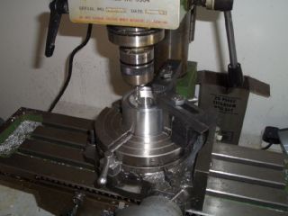
The next bit of machining has to be done on the milling machine and not the lathe. On the outer slot for the oil, part needs to be deeper in order to connect the rest of the slot with the 1/2" BSP drilling on the outside of the adaptor. But this can only go part of the way round - if it didn't, it'd break into the 1/2" BSP drilling which links up to the central oilway. Because the deeper part of the slot can only go part of the way round the workpiece it can't be (sensibly) done on the lathe, but has to be done on the mill using a rotary table.

The hardest thing, as usual, was getting everything lined up so that it was all reasonably concentric. At least on this occasion my rotary table wasn't manifestly too small for the job in hand, which is usually the case.
 

  The next job was to put the workpiece in the 4 jaw chuck so I could drill and tap some off-centre holes. The threaded holes are for 1/2" BSP threaded adaptors, and I machined the threads on the lathe.

The red lines on the workpiece are there because I was about to start the final step in the machining process and start removing the excess material from around the top of the take-off plate.

Having removed the excess material, I fitted the 1/2" BSP to -10AN JIC adaptors. I was pretty aggressive on the spacing of these to try and make the flow through the take-off plate as smooth as possible, and the adaptors needed machining slightly before they'd fit as they are so close together. The visible machining on the top one is from where I relieved the adaptor when I was still planning to use O-rings to seal them. However, the O-rings just buckle and distort, so I've used lashings of stud lock instead which should keep everything oil-tight.  

  At the bottom of the take-off plate I've tapped an M4 hole and fitted a short stainless button-head bolt. The tie-wrap you can see coming from the bottom of the take-off plate goes round the M4 bolt and then round the adjacent water pipe. This should stop the take-off plate from unloosening while it's in use.

The final job on this front is to fit the remote oil filter head, make up the hoses and connect the two up. However, the remote oil filter head still hasn't arrived from Think Auto, despite the fact that I ordered it nearly 5 weeks ago now. Last time I spoke to them they were 'being machined' so mine should be with me soon...
...and in fact it's now arrived. I welded a bracket onto the chassis to mount the remote oil filter head onto, with a view to keeping the oil lines as short as possible. The oil filter will be relatively heavy once it's full of oil, so I've added some gussets to try and keep the mount reasonably stiff.

With the mount in place, and given a quick coat of POR15, all that was left was to make up the hoses to connect the take-off plate and the remote filter head. As with the external sight glass, I've used Icore ProGold fittings with their Nomex/Kevlar braided hose, this time in a JIC -10 size, which should be more than large enough.
 

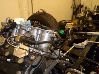
  And here it is all connected and ready to go. There's just enough space between the engine and where the side panels will go for the straight connectors to go on the take-off plate. It'd probably be better to have at least one of them as 90 degree fittings, but they're a lot more expensive and given the minimal clearances between the two fittings on the take-off plate, I'm not sure that a 90 degree fitting would necessary fit anyway.

The oil filter is now much more accessible. The filter that's on there at the moment is a standard BMC Mini filter although the filter head will take pretty much any filter with a 3/4" UNF thread. As the filter is hanging down from the filter head where I've mounted it, it doesn't need a non-return valve, and since the filter will be changed regularly (otherwise I've wasted a lot of time relocating the oil filter) a bypass valve shouldn't be necessary.

In the long run I suspect it shouldn't be too hard to find a much smaller filter which will fit onto the filter head, but this one will do for now.
 

Fuel tank

  As usual, the fuel tank's made by Alifab. And as usual, it's beautifully made, very reasonably priced, and delivered exactly when promised. I've mounted it using two steel straps underneath it to hold it in position, with various bits of ali angle/box section and foam to locate it laterally and longitudinally.

It's got a volume of about 30 litres, which should be more than enough for its use as a racer but will mean that I can use it on the road for longer runs if I want to, and it's not like the extra ali used in order to get the extra capacity weighs anything. It's internally baffled and foam filled, and although you can see it in this picture, it's got an enormous sump to prevent fuel surge (as I'm not fitting a swirl tank).

And as with any large flat(ish) surface, it's already proving handy as a work surface, as you can see...

Throttle cable

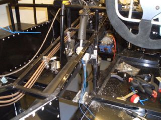
As a bit of light relief from oil filter take-off plates, I fitted the throttle cable. It's just a normal bike cable with the ferrule at the end filed down slightly, with a V-brake 'noodles' at either end. The end of the cable nearest the pedal is kept in place by a P-clip attached to the steering column bearing mount. Once I've fitted the airbox on the throttle bodies I'll add another fitting to hold the other end of the throttle cable.  

New wishbones

  And yes, I had already made wishbones for this car. And the wishbones I'd already made fitted perfectly on the Furybird II (unlike the Fisher wishbones made specifically for that car, which didn't). But the wishbones were too short for the (allegedly identical) front suspension on the FuryRacer - in order to get 2 degrees negative camber at the car's operating ride height required the rod ends at either end to be wound out to the point where there was rather a lot of thread showing. The inevitable result would have been bent rod-ends, so new wishbones were necessary.

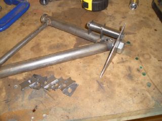
Taking advantage of this I added pick-ups for the front ARB I've decided to add - the picture on the left is of the little jig I made up for the ARB pick-ups.

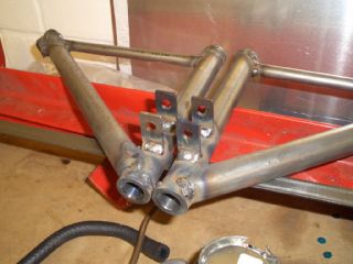
And here are the first two finished wishbones. I made four in total of this batch - two to fit, and two spares. Normally I'd be tempted to make only one spare, but these are handed due to the ARB mounts, so I need spares for each side.

They'll go off to be powder-coated along with the next batch of stuff - I'll wait until I've got a few more panels that need doing before sending the next lot off.

Hopefully they'll be the last wishbones I make for a while - I think 8 a year is enough...
 

Reverse gear lever

  The last part of the reverse mechanism to do (other than the wiring) was the reverse lever. The reverse mechanism is cable operated, so the lever has a bike brake cable going through it, and you can just about make out the cable stop I've added to the chassis upright at the side of the transmission tunnel.

The lever is another left-over from the Furybird - it's the only bit of carbon on the car (so far). The only mod I had to do to make it fit in the FuryRacer was to turn the right hand home-made pillow-block bearing round the other way and to make the aluminium dog-leg so the lever would clear the propshaft. The dog leg's machined from aluminium and has a slot clamp holding the upper part of the lever in place - for SVA I can remove it and fit something more SVA friendly.

However, for the rest of the time (much to the disgust of the GF) the reverse mech will be topped proudly by a joystick lever. And yes, the electric reverse does work by pressing the trigger on the joystick lever...

So now, I'm nearly in a position to finally fit the transmission tunnel side panels. I think I'll test the reverse mechanism properly under load first though...