This one's been causing me quite a few sleepless nights. The problem is the usual one with rear brake systems - getting a working and legal handbrake on the car. Naturally, I made things unnecessarily complicated for myself by deciding to try and use 2 part ali bell/iron rotor brake discs on the rear of the car as well as the front. This requires a disc of a certain size in order to squeeze it over the hub (even with the hub machined down) and doesn't leave to much room for a chunky OEM caliper with a handbrake mechanism.
One option was out from the start - no Sierra rear calipers. Can't stand the damn things, they're heavy, inefficient
and the handbrakes never seem to work properly. The other options were:
1. VAG calipers: These are found on MkIV Golfs, Passats B5s, Audi A3s and TTs and a whole host of VAG group cars. They're relatively light due to the ali body at 2170 with caliper carrier bracket but without pads of 2590 with pads (thanks to Craig for the weights). From a fairly cursory examination the handbrake seems reasonably smooth and potent. The downside is that they require quite a lot of room between the outside of the disc and the wheel. There is some potential for removing some of the ali from the top of the caliper, but even so I suspect that there wouldn't be much scope for using the 2 piece discs.
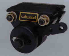
2. Wilwood spot caliper: The next option is to use a normal 2 pot caliper at the rear (probably a HiSpec ultralite 2) for the service brake and then a separate Wilwod spot caliper to provide the handbrake action. The Wilwood spot calipers are lightweight and cheap, but they're nasty. They're not especially effective and mounting them in any sensible way is a pain. They also, again, take up quite a bit of room between the disc and the wheel. I was tempted to go down this path for a while, but in the end I decided that it wasn't worth it, especially given the weight of the stainless steel bracket which would be required to hold them in place, and the fact that they don't have an integral mount for the handbrake cable.
3. Brembo handbrake caliper: The difficulties faced by kit car builders is also, it seems, faced by manufacturers of high performance sportscars like Aston Martin and Ferrari who want to fit 2 or 4 pot rear brake calipers. Brembo make a separate handbrake caliper as used on the Vanquish and 360 Maranello, which is also used on the Ultima when the big brake kit is fitted. The most obvious downside of these is the price - 275 pounds + VAT from Ultima for a pair. It also seems that they're quite heavy - Ted Marlow at Ultima e-mailed me to say that they weight 1950g each - that's nearly as much as a VAG caliper. They are a nice low profile, but at that price and weight they didn't seem like such a good option.

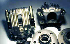
4. Alternative rear calipers: Given how everyone always complains about the Sierra rear calipers, it amazes me that so many kits use them. There are, after all, plenty of alternative rear calipers freely available at scrap yards all over the country. Given that I was making my own caliper mounts, I could use any caliper I wanted so I spent a few days inspecting the rear calipers of various cars while walking around. Fascinating...
I ended up ordering a pair of these. They're aluminium bodied, weight about 2600g with pads, have an integrated
handbrake caliper, and as you can see from the larger picture, don't have that much caliper outside the outer face
of the disc. I picked up a pair with brackets for 120 quid delivered inc VAT.
5. DIY handbrake option: A fifth
option, which is still at a very early stage and certainly won't be on the car from the outset is a custom made
handbrake mechanism. If you cross a mountain bike V-brake with the handbrake mechanism from a DeLorean, you'd be
getting close. If it works, it'll be feathery light, reasonably effective and very low profile, but there'll be
a lot of work to get there so it can wait for a while.
In the meantime, I'm going for option 4...
Once the rear hub spacers were machined up, I could do a trial fit with the Sierra hub carriers and hubs, the calipers
and the AP Racing rotors. This would confirm that my CAD model was reasonably accurate and give me a better idea
of the necessary dimensions of the rear brake bells. Happily my CAD model was almost totally accurate (less than
a mm out), so I could get one with making the rear brake bells.
However, the first thing to do was to turn down the rear hubs. I'm using AP Racing 254mm solid rotors for the rear
brakes, as they're biggest rotors I could (almost) guarantee would fit underneath the rims with the not-very-mystery
calipers. The trouble is, the internal diameter of the 254mm rotors was too small to fit over the rear hubs. Now,
that's not necessarily a show-stopper as
1. You shouldn't really have to take the brake discs off that often
2. It would be possible to make up a bell which would allow you to run rotors with a smaller internal diamater than the O/D of the hub, although it wouldn't be entirely straightforward.
3. You could, after all, if you were entirely deranged, have a system which required you to remove the rear hubs if you wanted to change the rear brake discs. Indeed, I understand that the Renault 19 suffers from precisely this, erm, idiosyncracy.
But, getting the rear hubs off a Sierra-based set-up is a right pain as the rear hubs are held on with one-use-only
gert big nylocs which have to be torqued up to faintly ridiculous levels according to Senor Haynes and his manual.
So, frankly, this seemed like a fairly crap idea.
 And
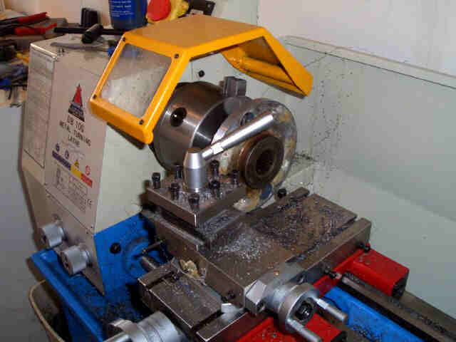
given that I'd just taken delivery of a nice big lathe, a much simpler solution presented itself fairly rapidly.
And here is said big lathe (it's a Chester Tools DB10G for anyone sad enough to be interested in such things) which,
with the help of some rather nice new indexable carbide tooling, had the excess off the rear hubs in a flash.
And
given that I'd just taken delivery of a nice big lathe, a much simpler solution presented itself fairly rapidly.
And here is said big lathe (it's a Chester Tools DB10G for anyone sad enough to be interested in such things) which,
with the help of some rather nice new indexable carbide tooling, had the excess off the rear hubs in a flash.
The rear hubs are off a drum-braked Sierra, so as well as the splined holes for the wheel studs they've got the
larger holes in them for access to the hub carrier bolts. The outside edges of these are quite a bit closer to
the edge of the standard hub than the outside edges of the holes for the wheel studs. In the end, I ended up turning
down the rear hubs to within about a millimetre of the outside edge of the access holes, but it was *just* enough
to allow the hubs to squeeze inside the rear brake discs.
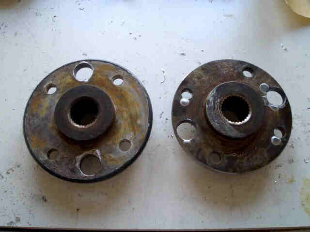 Here's the traditional
'before and after'. You can see from this picture how much I had to take off, and also how close I had to get to
the edge of the access holes. Machining steel (or whatever the hubs are made out of) is a lot harder work than
the ali I've been working with until now...
Here's the traditional
'before and after'. You can see from this picture how much I had to take off, and also how close I had to get to
the edge of the access holes. Machining steel (or whatever the hubs are made out of) is a lot harder work than
the ali I've been working with until now...
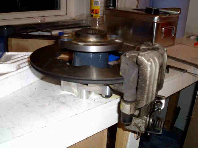
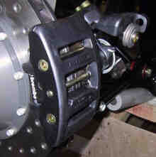
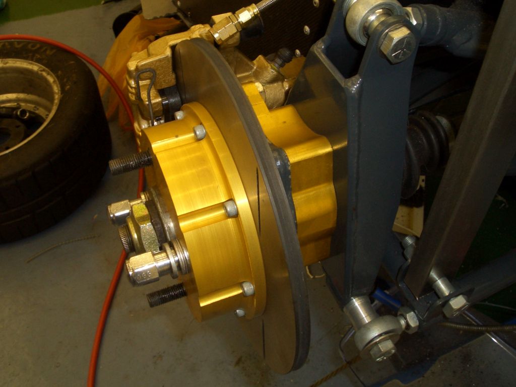
This picture shows the rear brake setup without the brake bell. At the bottom you can see the hubspacer which I machined. The caliper is the MINI caliper and the disc is the AP Racing 254mm solid disc. The dark grey bit is the Sierra hub carrier and on top of that you can see the turned-down hub itself.
Now all that's required is a brake bell to connect the hub to the brake disc. From this dry run, it looked as though
there were no major flaws in my plan...
Once I was satisfied that the plan was going to work, at least in principle, it was time to start work properly
on the rear brake bells. The starting point was a very large lump of ali bar, 7" in diameter and 6" long.
Which I got shipped from the States. Well, I bought it on eBay...
There was actually a good reason for paying for a large and otherwise devoid-of-interest lump of ali to be taken
on a world cruise. One of my technical books ('Engineer to Win' by Carroll Smith) says that for brake bells you
should use 2024-T356 ali. Although 2014-T6 and 7075-T6 are stronger at room temperature, brake bells get very hot
as the ali is rather good at conducting heat away from the rotors. And if you want ali that stays strong at elevated
temperatures, then apparently 2024-T356 is the Daddy. So 2024-T356 it had to be.
Despite being assured by every man and his dog that it was impossible to walk down your average High Street without
tripping over large lumps of 2024-T356 being sold by 2024-T356 shops, I found it impossible to get any in this
country. Well, that's not quite true. If I'd wanted a couple of tons of the stuff, I wouldn't have had a problem.
However, since I wanted to use the stuff to make 4 brake bells rather than an extension for the house machined
from billet, a couple of tons was about 1.99 tons more than I need. Hence the purchase of the stuff from the land
of the Merkins via eBay. And hence the reason why the shipping cost more than the metal itself.
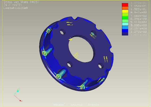 I designed the rear brake
bells using my Wildfire 2.0 CAD package. Wildfire (at least the version I've got) includes an FEA package called
Pro/Mechanica. It's extremely easy to use and (apparently) is pretty accurate. Given that a brake bell is not something
that you want to fail, I decided that it was probably worth doing a few FEA design studies to make sure that the
design was going to be strong enough.
I designed the rear brake
bells using my Wildfire 2.0 CAD package. Wildfire (at least the version I've got) includes an FEA package called
Pro/Mechanica. It's extremely easy to use and (apparently) is pretty accurate. Given that a brake bell is not something
that you want to fail, I decided that it was probably worth doing a few FEA design studies to make sure that the
design was going to be strong enough.
I set up the FEA to analyse a real worst case scenario - the constraints and loads in the FEA was equivalent to
a 1G retardation of the whole car going through only one wheel, with the bolts holding the rotor onto the brake
bell loose (with the result that you get point loads around the bolt holes rather than the load being spread all
over the mounting face). Even with a safety factor of 3 the FEA assured me that a wall thickness for the brake
bell of 4.5mm would be enough. Erring, as ever, on the side of caution, I'm going for 6.5mm, which gives me a safety
margin of over 10.
The next problem was getting this large cylinder of ali chopped up into slices - 2 x 47mm high, 2 x 16mm high.
Naively I'd assumed that one of the local engineering places would be able to do this for me. Nope. The precision
engineering places couldn't handle material that big (eh?). The places that did have machines large enough to chop
it up thought that the 6" long piece I was waving at them was an offcut of the 6 foot long bit I wanted chopping
up. I eventually found one place that said it could do it in Soham, but they turned out to be a bunch of inbred
Fendwellers who, after I'd schlepped all the way over there, decided that they couldn't after all. Thanks guys...
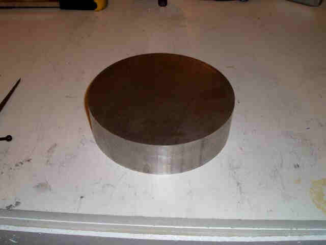 As ever, cam7 came to the rescue in the form of Dave Turner. Dave seems to have access
to vast numbers of expensive and under-used workshop machinery, but even the kit at his disposal couldn't do the
trick. However, he knew a man who could, so the 6" long bar of ali got chopped into 4 sections, 2 thick and
2 thin. And here's a thick one, ready to be turned (mostly) into swarf...
As ever, cam7 came to the rescue in the form of Dave Turner. Dave seems to have access
to vast numbers of expensive and under-used workshop machinery, but even the kit at his disposal couldn't do the
trick. However, he knew a man who could, so the 6" long bar of ali got chopped into 4 sections, 2 thick and
2 thin. And here's a thick one, ready to be turned (mostly) into swarf...
 The bar had been cut using
a bandsaw and although the faces of the bar were fairly level, they weren't exactly level. So the first step was
to put the bar on the milling machine and face both ends to make sure they were flat and parallel.
The bar had been cut using
a bandsaw and although the faces of the bar were fairly level, they weren't exactly level. So the first step was
to put the bar on the milling machine and face both ends to make sure they were flat and parallel.
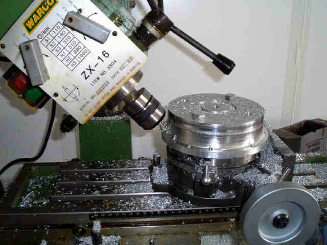
The rear brake bells are a maximum of around 160mm in diameter, so there's a fair amount of material to take off
the edge. However, this requires the use of the rotary table, and given that my rotary table's got a 6" diameter,
and this piece of bar has a 7" diamater, you have to be a bit creative when clamping it to the table. Holding
a workpiece in place is almost always the biggest problem when machining stuff (other than the challenge, sometimes,
of keeping awake during long boring milling operations).
 In the end I drilled a 10mm
hole down the middle of the ali bar and used this as a central spigot. This kept the plate central on the rotary
table, as the rotary table had an MT2 taper insert in its centre with the end turned down to a 10mm diameter. Then
it was just a case of drilling 4 10mm holes roughly where the holes for the wheel studs would go. I then used M10
bolts to bolt the workpiece down onto the rotary table using M10 nuts in the slots in the table normally used for
T-nuts.
In the end I drilled a 10mm
hole down the middle of the ali bar and used this as a central spigot. This kept the plate central on the rotary
table, as the rotary table had an MT2 taper insert in its centre with the end turned down to a 10mm diameter. Then
it was just a case of drilling 4 10mm holes roughly where the holes for the wheel studs would go. I then used M10
bolts to bolt the workpiece down onto the rotary table using M10 nuts in the slots in the table normally used for
T-nuts.
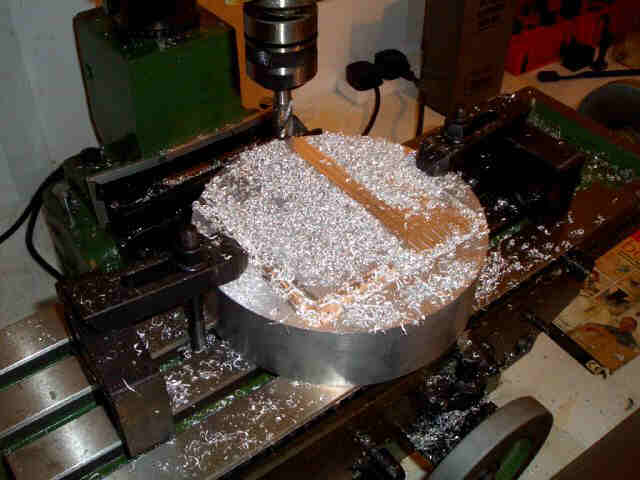
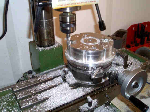
In the picture on the left you can see the workpiece clamped in place. Here, I'm milling out the central hole on
the brake bell which the spigot on the hub will fit through. It's only necessary at this stage to mill the circular
slot as deep (actually a bit deeper than) the depth of the mounting face of the bell.
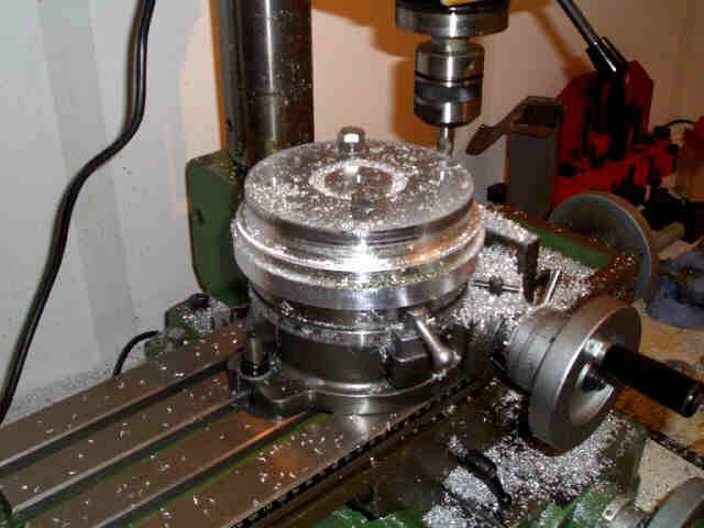
 Then it was time to machine
the excess material away on the outside of the bar. Unfortunately, because of the depth of the workpiece, I couldn't
do this with it kept in one position on the rotary table, as the milling cutters I've got aren't long enough and
the chuck starts to hit the top of the workpiece. As a result, it was necessary to do the top section, and then
turn the workpiece over and machine the mounting flange which the rotor will fit onto separately.
Then it was time to machine
the excess material away on the outside of the bar. Unfortunately, because of the depth of the workpiece, I couldn't
do this with it kept in one position on the rotary table, as the milling cutters I've got aren't long enough and
the chuck starts to hit the top of the workpiece. As a result, it was necessary to do the top section, and then
turn the workpiece over and machine the mounting flange which the rotor will fit onto separately.
Boring boring boring. And it produces vast piles of swarf, which you can see building up on the milling machine
table. Doing one brake bell produces about 12 litres of swarf by volume...
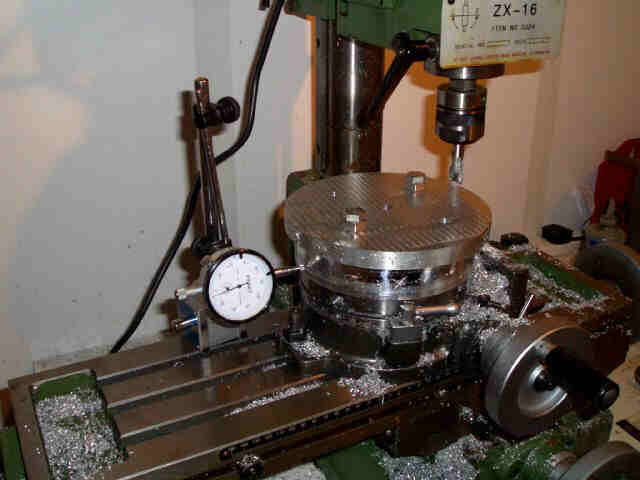 In order to make sure that
the flange is concentric with the body of the rear bell, I used a dial gauge to make sure that the 10mm hole used
to centre the bar on the rotary table was exactly central. It wasn't *quite*, but a few taps with a gentle persuade
soon got it right. Well, not exactly spot on - I decided that for this job I'd work for concentricity to within
0.1 mm. I reckon that's accurate enough for this job.
In order to make sure that
the flange is concentric with the body of the rear bell, I used a dial gauge to make sure that the 10mm hole used
to centre the bar on the rotary table was exactly central. It wasn't *quite*, but a few taps with a gentle persuade
soon got it right. Well, not exactly spot on - I decided that for this job I'd work for concentricity to within
0.1 mm. I reckon that's accurate enough for this job.
 Once the outer edge of
the rotor mounting flange so that the bell fitted snuggly within the disc, I could place the disc over the bell
and drill the mounting holes. Using the rotor as a template of course meets that you can guarantee the holes in
the bell will be in the right place. These are 1/4" (AP claim they're 6.4mm but that's obviously a metrification)
and again, the holes only need to be drilled as deep as the mounting flange, as the excess material will be machined
away later.
Once the outer edge of
the rotor mounting flange so that the bell fitted snuggly within the disc, I could place the disc over the bell
and drill the mounting holes. Using the rotor as a template of course meets that you can guarantee the holes in
the bell will be in the right place. These are 1/4" (AP claim they're 6.4mm but that's obviously a metrification)
and again, the holes only need to be drilled as deep as the mounting flange, as the excess material will be machined
away later.
I used a drill chuck in the mill to drill these holes, rather than using the pillar drill - it's handy being able
to use the X-Y table to accurately locate the drill, and I don't have an X-Y table (yet) for the pillar drill.
Probably out to though - it'd make it a lot more useful.
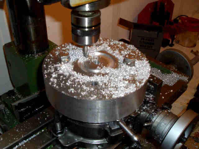
 Once the holes were drilled,
it was time to machine away the excess on the body of the bell. Once again, boring as hell and loads of swarf.
Thankfully there wasn't quite as much to take off as the first cut, so I could take slightly deeper cuts and speed
the whole thing up a bit. I left it slightly oversized so that I could put the roughly-cut bell on the lathe and
do a few finishing cuts to improve the cosmetics.
Once the holes were drilled,
it was time to machine away the excess on the body of the bell. Once again, boring as hell and loads of swarf.
Thankfully there wasn't quite as much to take off as the first cut, so I could take slightly deeper cuts and speed
the whole thing up a bit. I left it slightly oversized so that I could put the roughly-cut bell on the lathe and
do a few finishing cuts to improve the cosmetics.
 The finished item is going
to be a lot stronger if there are nice big radii on all the corners. The area where the rotor mounting flange meets
the body of the bell is going to be particularly stressed, so I wanted to put as big a radius here as was reasonably
practical.
The finished item is going
to be a lot stronger if there are nice big radii on all the corners. The area where the rotor mounting flange meets
the body of the bell is going to be particularly stressed, so I wanted to put as big a radius here as was reasonably
practical.
The easiest way to do this (without using the lathe and a ball-turning tool) was with a ball-ended cutting on the
milling machine. The head of the milling machine can be rotated to any angle and while this is normally a right
royal PITA (because the nuts loosen off due to vibrations and the head starts making a rotational bid for freedom)
it can be handy for times like this.
Unfortunately this is a totally pony photo so you can't really see the radius. Trust me, it's there.
 The last job to do before
hacking out the inside of the bell was to machine some slots on the outside of the bell, where the bolts are going
to go. Because there's such little space between the outside edge of the hubs and the mounting points on the rotor,
the body of the rotor has to be machined to allow the bolt heads space to breathe.
The last job to do before
hacking out the inside of the bell was to machine some slots on the outside of the bell, where the bolts are going
to go. Because there's such little space between the outside edge of the hubs and the mounting points on the rotor,
the body of the rotor has to be machined to allow the bolt heads space to breathe.
The machined almost-semi-circular slots go down to the top of the rotor mounting flange and form a recess which
the bolt head can sit in. It's necessary to machine this otherwise the bolt head would be sitting on the radius
machined above. The largest end-mill I had which wasn't totally blunt was a 12mm one, and the washers which AP
supply for use with their 6.4mm bolts are slightly over 12mm, so I put a whole load of them on a bolt, put the
bolt in the lathe, and turned them all down to 11.5mm.
 Once the outside of the
bell was roughed out, it was time to remove the material from the inside. I again used the rotary table to do the
round cut on the inside, and then just the X-Y table to remove the material from the middle. Took hours of course,
and was extremely dull.
Once the outside of the
bell was roughed out, it was time to remove the material from the inside. I again used the rotary table to do the
round cut on the inside, and then just the X-Y table to remove the material from the middle. Took hours of course,
and was extremely dull.
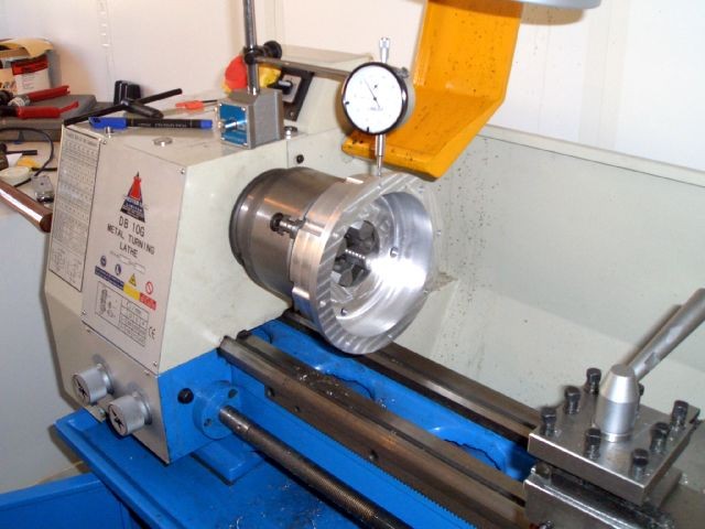
Once the milling was finished, I transferred the bell onto the lathe for a final once-over to make sure everything
was true. In order to get things as accurate as possible I used a 4-jaw chuck and again used a dial gauge to make
sure everything was true and level.
 Here's a photo of the bell
at the beginning of the work on the lathe. You can see that the cross-hatched finish on the bottom of the bell
has gone and that the inside is looking shinier - this is due to the smoother finish the finishing cuts of the
lathe give than the rough work on the mill.
Here's a photo of the bell
at the beginning of the work on the lathe. You can see that the cross-hatched finish on the bottom of the bell
has gone and that the inside is looking shinier - this is due to the smoother finish the finishing cuts of the
lathe give than the rough work on the mill.
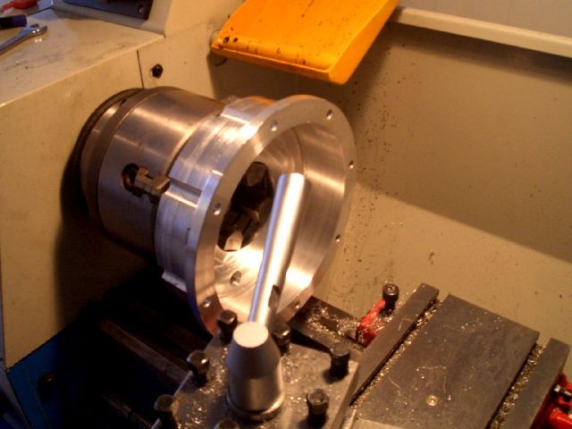
I ended up having to use some fairly funkily shaped cutting tools that I made myself from HSS tool steel. This
was due to the fact that the bells are getting to the limit of what I can machine on my lathe - there's plenty
of space for them to swing above the bad, but for instance the cross-slide won't fit underneath a work-piece this
big - so if you want to machine the outside of the bell in this position at the end closest to the chuck, you need
a tool which will get there from the tool-post.
Eventually all the machining was complete and the only thing left to do was to get the bells (front and rear) and
the upright spacers anodised. I got this done at Peterborough Plating who did it for a very reasonable 30 quid
for all of them.
Then, once the bells are bolted to the rotors, they can be fitted onto
the rear hubs.
Pretend the caliper isn't there - again, these photos were taken a bit out of sequence...
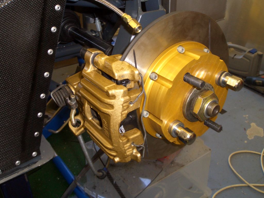 |
Then it was time to fit the rear calipers. To end the suspense, they're
from a new model BMW MINI - they're made by ATE and while they're not as light as a full ali caliper, and are still
slider calipers, they're not a bad option IMHO. The only thing I've done to them is to paint them this rather fetching gold colour, to (supposedly) match the other gold-anodised suspension and brake parts. The paint finish isn't exactly the neatest in the world, but then again (as later pictures show) you can't really see much of them once the wheel is fitted. I ended up having to fit a cut-down bolt into the bottom mounting point on the caliper as there wasn't enough space to get a bolt between the caliper mount and the upright. So I inserted a bolt into the caliper and ran a bit of weld over the end of the bolt to turn it into a mounting stud. |
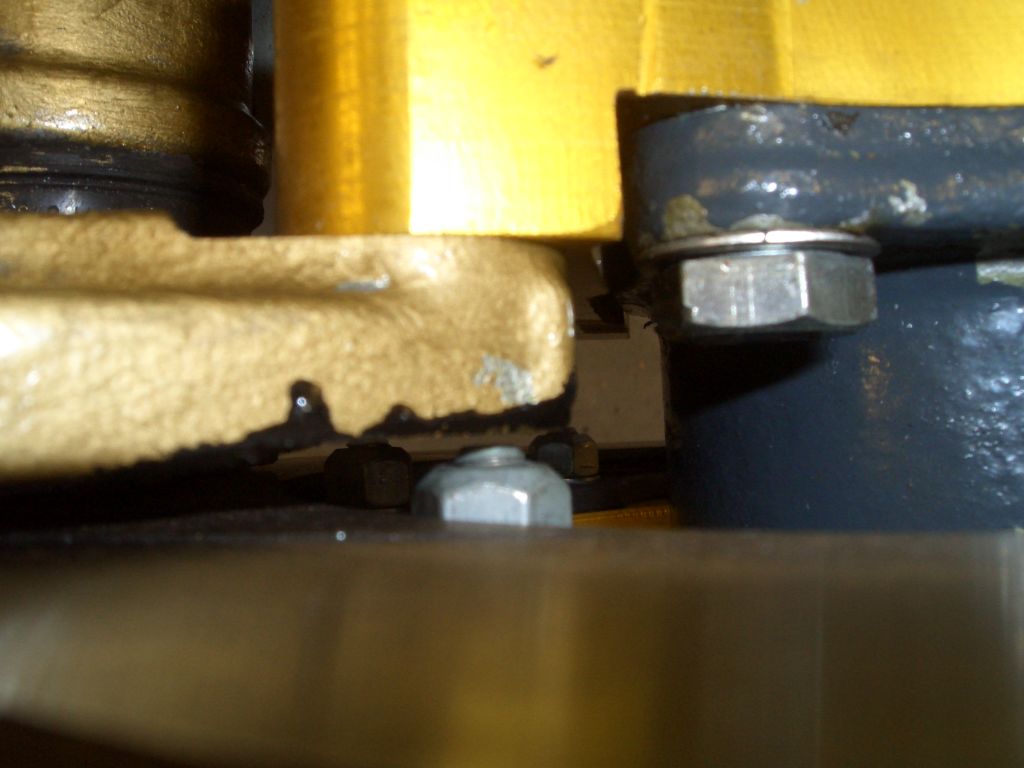
| I also had to machine a bit off the steel part of the caliper which
bolts to the upright and which holds the sliders which the ali part of the caliper mounts onto. Otherwise the
ends of the bolts which bolt the bell to the rotor fouled the caliper. It only needed less than a millimetre taking
off, though, and there's plenty of meat left on the caliper. As you can see, there's precious little clearance even with a bit of caliper machined away. The black streaks are from the POR15 I've used to paint the machined areas - I'd run out of the gold paint... |
 |
 |
As I mentioned, you can't see much of the caliper with the wheel on, but all in all, I reckon it looks suitably pimpy. |
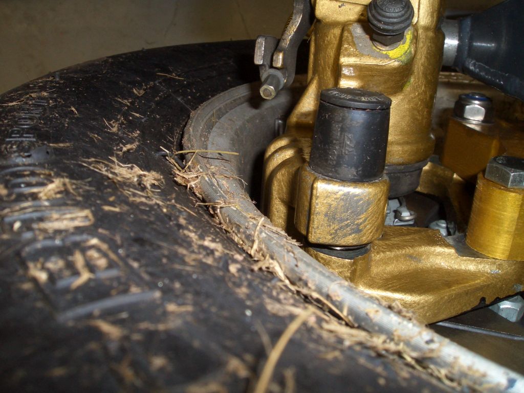
| There's not all that much clearance between the caliper and the wheel,
but there's enough. Generally, there's not a great deal of clearance with this caliper/rotor/wheel combination,
but as the CAD work predicted, it does just all about fit. The grass on the tyre is left over from my little incident on Mallory - a new set of AO21Rs is on order to replace the ACB10s. |
 |
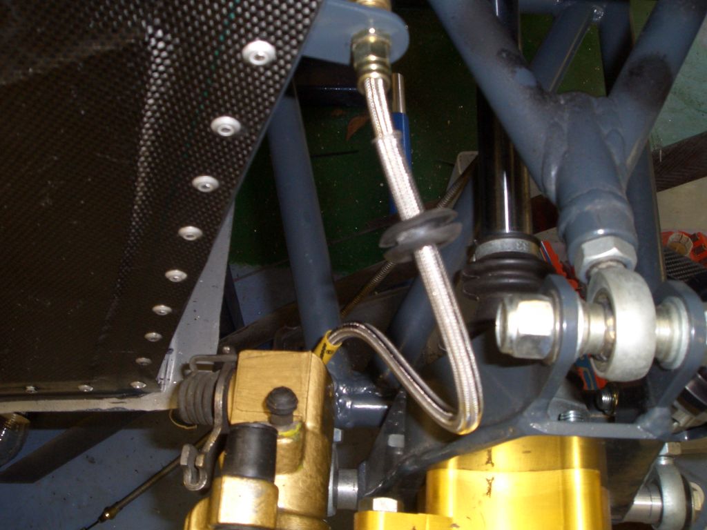 |
The last thing to do was to make up and fit the rear brake hoses.
The MINI calipers take an M12 banjo bolt fitting. I couldn't find any M12 fittings for DIY brake hoses, so I ended
up buying a set of MINI stainless-steel braided hoses from Goodridge. The Rally Design Euroquip fittings are compatible
with the Goodridge hoses, so I kept the Goodridge M12 banjo on one end, and added an M10 bulkhead Euroquip fitting
on the other end. It's a sign of the minimal clearances there are to play with that you can't get access to the banjo bolt on the caliper with the suspension at full droop - in order to tighten the banjo bolts you have to raise the suspension. Still, I hope they all stay nice and tight - fingers crossed... |