 Like the front suspension, I'm using rosejoints on all the rear suspension bushes. Again,
I'm not using the standard Fisher supplied units, but rather highly quality units from Autosport Bearings. These
a 3 piece 1/2" UNF x 1/2" UNF units, and I've also used spacers from Rally Design to mount the rosejoint
heads in the brackets on the chassis and on the uprights. It's necessary to use washers even so to fill the space
inside the brackets. Eventually I may turn up some spacers which fit exactly (which would certainly come in handy
if I ever need to adjust the rear suspension. However, it's not a priority at the moment.
Like the front suspension, I'm using rosejoints on all the rear suspension bushes. Again,
I'm not using the standard Fisher supplied units, but rather highly quality units from Autosport Bearings. These
a 3 piece 1/2" UNF x 1/2" UNF units, and I've also used spacers from Rally Design to mount the rosejoint
heads in the brackets on the chassis and on the uprights. It's necessary to use washers even so to fill the space
inside the brackets. Eventually I may turn up some spacers which fit exactly (which would certainly come in handy
if I ever need to adjust the rear suspension. However, it's not a priority at the moment.
Follow up: In fact, I did turn
up some spacers on my little Unimat 4 lathe which means I no longer have to use the large piles of washers. And
very nice they are too.
 After I'd put the arms roughly
in position, I provisionally set up the rear suspension - it's easier to do it now, at least to provide a base
level to work from, than when the bodyshell and assorted gubbins are in place. To do this I worked out the ride
heigh I'd be aiming for, and made up some steel struts to use instead of dampers during the build (still thinking
of getting some new Nitrons rather than using the old ones) and to keep the rear wheels in the right place during
the build. They're so exciting, these lengths of steel with two holes in them, that I've included a picture...
After I'd put the arms roughly
in position, I provisionally set up the rear suspension - it's easier to do it now, at least to provide a base
level to work from, than when the bodyshell and assorted gubbins are in place. To do this I worked out the ride
heigh I'd be aiming for, and made up some steel struts to use instead of dampers during the build (still thinking
of getting some new Nitrons rather than using the old ones) and to keep the rear wheels in the right place during
the build. They're so exciting, these lengths of steel with two holes in them, that I've included a picture...

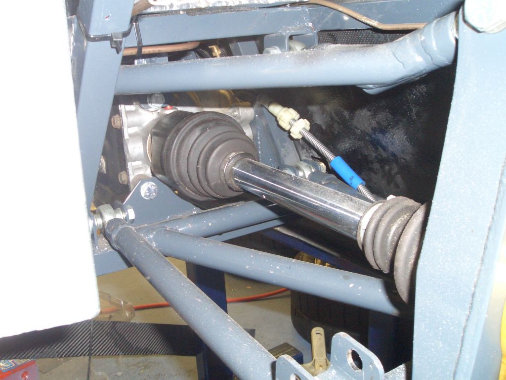
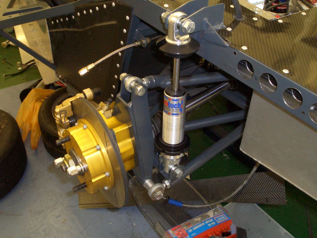
The standard Fury rear suspension uses spacers in between the rear upright and the Sierra hub carrier. These are the gold anodised aluminium bits you can see in the picture on the right. They're each around 16mm wide, and the Freelander IRS set-up uses two spacers to increase the rear track.
The standard set-up with calipers uses a steel bracket mounted on the outside face of the hub carrier, and the
brackets are designed to take a Sierra rear handbrake caliper. I'm using MINI rear calipers so I wouldn't be able to use
these anyway. Also, having two spacer seems inelegant - nothing wrong with it per se, but I'd rather just use one.
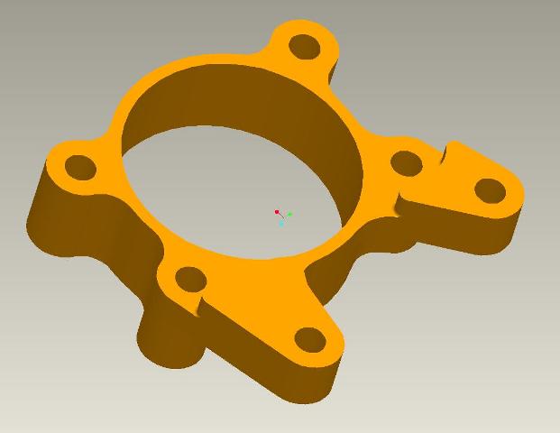
So the obvious thing to do is to make my own hubspacers, 32mm deep, with integral caliper mounts for the MINI calipers.
 I'd got
a new CAD system to use (PTC Wildfire 2.0) so I designed the hubspacers with that. The design as I finally made
it wasn't quite the same, but the design still proved to be useful as a reference.
I'd got
a new CAD system to use (PTC Wildfire 2.0) so I designed the hubspacers with that. The design as I finally made
it wasn't quite the same, but the design still proved to be useful as a reference.
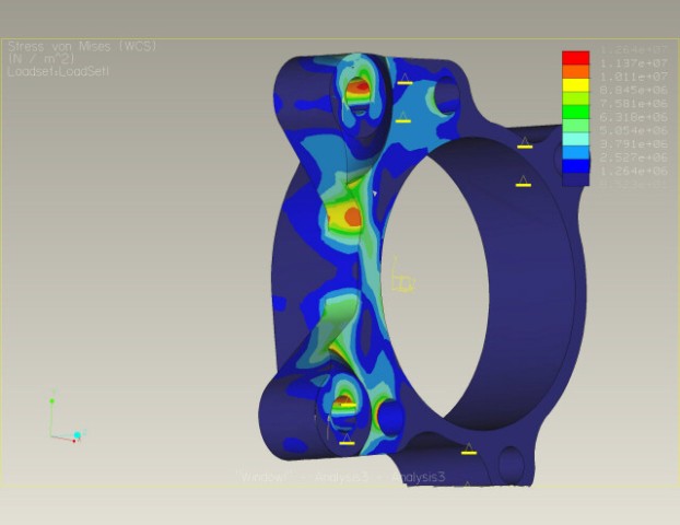 Clearly, a part which holds the rear wheels on and
the rear calipers in place is fairly mission critical, and not something you'd want to fail. Playing on the safe
side (aluminium's pretty light after all) I used a few, ahem, rules of thumb and then added a bit. Not particularly
technical, but I made up for that by doing a few FEA, erm, thingies*. By doing this I could identify the most stressed
part of the design and could check that it was within the limits of the material (6082-T6). Which it was, by an
order of magnitude. Which is nice. As is the pretty picture showing the Van Mises stresses...
Clearly, a part which holds the rear wheels on and
the rear calipers in place is fairly mission critical, and not something you'd want to fail. Playing on the safe
side (aluminium's pretty light after all) I used a few, ahem, rules of thumb and then added a bit. Not particularly
technical, but I made up for that by doing a few FEA, erm, thingies*. By doing this I could identify the most stressed
part of the design and could check that it was within the limits of the material (6082-T6). Which it was, by an
order of magnitude. Which is nice. As is the pretty picture showing the Van Mises stresses...
 Now it was simply
a case of making the damn things. I had planned to simply send my CAD file off to a nice man with a CNC mill and
get him to knock of a LHS one and a RHS one. Unfortunately, this plan turned out to be rather optimistic, as the
cheapest quote I got was for £250+VAT each. If I'd wanted 20, of course, the price would be down to 40 quid
each, but I'm not sure anyone else wants one given my rather eclectic choice of braking components. So I bought
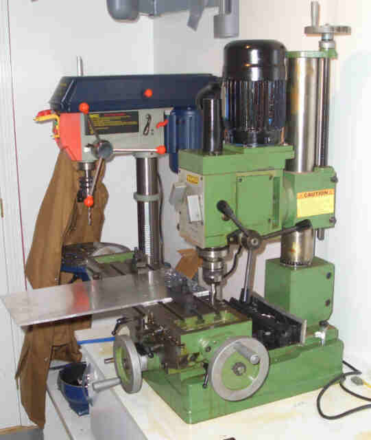
a milling machine instead.
Now it was simply
a case of making the damn things. I had planned to simply send my CAD file off to a nice man with a CNC mill and
get him to knock of a LHS one and a RHS one. Unfortunately, this plan turned out to be rather optimistic, as the
cheapest quote I got was for £250+VAT each. If I'd wanted 20, of course, the price would be down to 40 quid
each, but I'm not sure anyone else wants one given my rather eclectic choice of braking components. So I bought
a milling machine instead.
eBay, of course. And sadly, despite being described as being in 'excellent' condition, it turned out to be well
and truly knackered. I won't bore you with the details of what it needed to get it fixed, but it took a while and
was very boring. Still, even with the expense of the spare parts to fix it, the total still came to less than the
cost of the CNC'd hubspacers. Mind you, tooling and a Pozilock collet system don't come cheap.
And for the extremely dim, it's the green one that's the milling machine...
 So, for this recipe you will
need a milling machine, some end mills and slot mills, and 2 lumps of 125mm x 125mm x 43mm 6082-T6 ali, and some
cutting fluid. What you will mostly make with all this is swarf.
So, for this recipe you will
need a milling machine, some end mills and slot mills, and 2 lumps of 125mm x 125mm x 43mm 6082-T6 ali, and some
cutting fluid. What you will mostly make with all this is swarf.
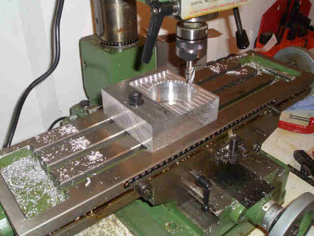
I cut the big hole for the hub carrier to sit in by stitch-drilling it on the pillar drill. Then put in on the
rotary table and gave it a quick whizz round to remove all the edges of the holes and a few extra whizzes to bore
it out to the right size. You can see the evidence of the stitch drilling around the top of the large hole. In
this picture I'm milling away the face of the spacer that the hub carrier will sit on. The higher bit to the left
of the picture (with the nut on it) will make up the part which the caliper attaches to.
 And after sodding hours of turning the handles on
the milling machine, taking the ali away 1mm at a time, there's a hole the hubcarrier can sit in. Hurrah!
And after sodding hours of turning the handles on
the milling machine, taking the ali away 1mm at a time, there's a hole the hubcarrier can sit in. Hurrah!
The original design for the hubspacer is slightly different from what I ended up making. The orignal design has
the outside face of the spacer part in a circle - when it came to it I decided to make it so that it followed the
outside shape of the Sierra hub carrier.
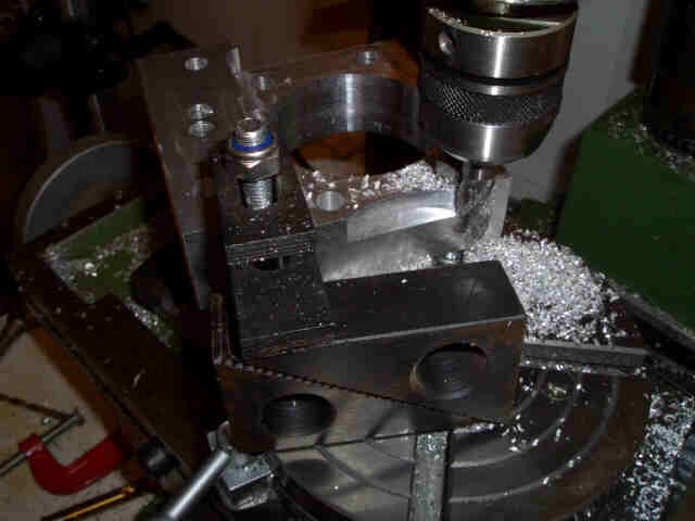 To get the curved outside edges right,
I used the rotary table I'd bought. As usual when using a milling machine, the hardest part is working out how
to clamp the workpiece in place. Especially when you're using tools which aren't really big enough for the things you're machining. The rotary table is only a 6 inch model and,
as you can see on the picture on the right, at times there was more of the workpiece hanging off the rotary table
than was securely clamped to it...
To get the curved outside edges right,
I used the rotary table I'd bought. As usual when using a milling machine, the hardest part is working out how
to clamp the workpiece in place. Especially when you're using tools which aren't really big enough for the things you're machining. The rotary table is only a 6 inch model and,
as you can see on the picture on the right, at times there was more of the workpiece hanging off the rotary table
than was securely clamped to it...
For this machining I've used a 12mm or 14mm end mill. There were a couple of times when a slot mill would have
been more appropriate, but quite frankly I couldn't be bothered to change tooling and the end mill was OK for what
was required.
 This picture shows a later
stage in the machining where I'm still machining the edges of the spacer to suit match the outside edges of the
Sierra hub carrier. You can see where I've drawn round the edge of the Sierra hub carrier and I'm simply machining
curves to match those lines. It's not exactly precision stuff, but then again it doesn't really need to be.
This picture shows a later
stage in the machining where I'm still machining the edges of the spacer to suit match the outside edges of the
Sierra hub carrier. You can see where I've drawn round the edge of the Sierra hub carrier and I'm simply machining
curves to match those lines. It's not exactly precision stuff, but then again it doesn't really need to be.
Lining up the curves is actually quite easy - the rotary table has a series on concentric rings machined in it,
and the curves on the hub carrier seem to match one of these rings fairly closely. It's therefore fairly simple
to align the workpiece.
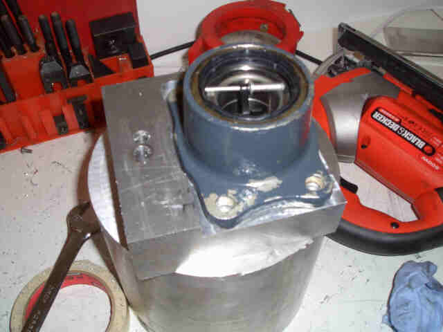
Once I'd finished machining the spacers, I got them anodised gold and
installed them on the uprights, along with the hub spacers and brake bells. In this much later picture you can
see the spacer bolted between the hub carrier (which you can just see to the left of the spacer) and the upright.

Last thing to do is fit the dampers and springs. Dampers are fitted,
springs are still to be ordered.
Things to do: Fit springs to dampers
and check rear hub nuts. Wind spring seats into roughly the right position, put on the floor and check toe and
camber.
* Of course most people would say 'FEA analysis' but this is a tautology
and so cam7
would direct huge heaps of derision my way if I did that...