31st July 2010

Top rocker arms

One of the pieces I needed to replace as a result of the crash was the near-side top rocker arm. There are two different types of rocker arms used on Furies, which relate to the two different types of Escort-based uprights (some cars also used Sierra uprights, but I'll ignore them for the moment). Some of the uprights have a taper in the top of the upright, and use a Chevette ball joint mounted onto the top rocker arm with two M10 bolts. The more recent ones use a threaded insert in the top of the upright, and have a Metro balljoint screwed into the top of the upright. This then mounts into a taper in the end of the rocker arm. The Chevette-jointed rocker arms tend to be made of sheet steel, the Metro-jointed ones tend to be tubular.

Because I was reusing the old Chevette-style uprights on the FuryRacer, previously used on the FuryBird, when I ordered the Furybird chassis I also ordered two Chevette-balljoint style top rocker arms. These are a sort of hybrid - they're tubular like the more modern rocker arms, but they're made to have the Chevette balljoint bolted onto them. They took for ever to source first time round, and so I wasn't particularly sanguine about the prospects of being able to get a replacement in a timely manner from Fisher/BGH. So, I took the good rocker arm off the unbent side of the car, and started using as the basis for a jig, so I can make up as many top rocker arms as I like.
 

Jig


And here is the jig. Yep, it's not exactly pretty, but the key thing is that it's very rigid and holds everything in place while it's welded together. The central tube is held in place using the studding and the aluminium spacers, the damper mount is held in place using the bolt on the right hand side of the jig, and the Chevette balljoint mount takes its position on the left hand side of the jig. The strips of angle iron are to keep the outer tubes connecting the central tube and the balljoint mount in the right place.

The central tube on the top rocker arms is 1 1/2" 10 gauge CDS tubing. That's got an wall thickness of 3.2mm, which seems rather thicker than is strictly necessary. On the old/existing top rocker arms, the central tube has in fact been made up by using some 1 3/8" 16 gauge tubing (ERW stuff from the look of it) with some 1 1/2" 16 gauge stuff slipped over the ends and welded into place in order to increase the wall thickness where the tubes mount ono the central tube.

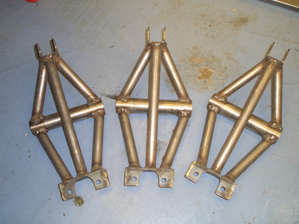
And here, as they old saying goes, is one I made earlier. I've turned down the central section of the central tube on the lathe (probably pointless, but what the hell) to replicate the fabricated central tube of the bent rocker arm. The damper mount bracket isn't something I've made - I bought it from 3GE components, who make parts for the new Locostesque Haynes Roadster. It's their part number SUS2, and at £1.90 each it makes making up suspension brackets look like a thoroughly unworthwhile job. Even better, their website works, they take payment via Paypal, and they deliver stuff very promptly, so I suspect I'll be using them again.

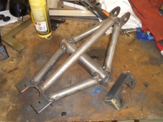
This top rocker arm isn't quite finished. It's only tack-welded in places, and there are a couple of reinforcing plates to go in the balljoint mount on the left hand side - a mount with the side plates welded in place is on the right hand side of the photo.

The tubes on the top rocker other than the central tube are the usual 22mm/7/8" 16 gauge CDS tubing which Tim and I use for wishbones. It's fatter than the tubes used in the standard Fisher wishbones, but if previous experience is anything to go by, it'll be considerably thinner wall thickness. I'll try weighing one of my rocker arms and one of the Fury manufactured ones to see who they compare.

As usual with replacement parts, I've aimed for an accurancy of +/- .5mm, on the basis that this is significantly more accurate than the standards to which the chassis was constructed. The rocker arms I've made are certainly an accurate reproduction of the Fisher ones - they even accurately replicate the fact that on the Fisher top rocker arm the balljoint mount isn't mounted squarely when compared to the central tube...


  One very very thin silver lining to the cloud of having to make new top rocker arms was that it would give me an excuse (if any excuse were needed) to use my new tube notcher. Tim's had one for ages, and I've used it a few times making wishbones and the like. So I when I spotted some being sold by Chester Tools for a bargain price on eBay I decided to buy one on spec to keep to one side for a rainy day.

Big mistake. It's a total PoS. My lathe is made by Chester Tools, as is Adrians', and while they're not exactly precision machinery they're good value for money and perfectly adequate for the kind of stuff we're doing. The tube notcher, on the other hand, is appallingly bad. First off, the plain bearings that the rotating shaft rotates in were horribly oversized, by about 0.3mm, which meant that the shaft would rock up and down, sending the hole saw moving around all over the place. So I ended up having to knock them out and replace them with some home-made aluminium bushes (I didn't have any bronze bar of the right size) which you can see in the photo.

That got rid of the horrific run-out when using the thing, but didn't solve the fact that the clamp doesn't actually hold the tube you're working on in line with the hole saw - the centre line of the tube ends up about 1.5mm lower than the centre line of the hole saw. This will require me to shim then entire clamp (which pivots to allow you to alter the angle of the tube you're working on) just to get the thing to work even half-decently.

Moral of the story - don't buy Chester Tools tube notchers, 'cos they're rubbish...


However, despite the unnecessary faffing around caused by making the tube notcher work in vaguely the manner it's supposed to, I've now finished off making 3 new top rocker arms (one for each side, one spare, and the old Fisher-supplied one as an emergency spare). I've also made up two new Panhard rods (one to fit, one spare, and the straightened one from the crash as an emergency spare spare) because they take about 10 minutes each to make.

Next up is the replacement lower trailing arms for the back end of the car. But before continuing with the suspension manufacturing a quick update on the bodywork repairs...
 

Pretty fly for a black bonnet...

Having pieced together the bonnet, the next job was to transfer it to the Shed to fill and sand it into shape and then paint it. I'd previously transported bonnets to and from the Shed by mounting them on the Scooby's roof bars, and so thought I'd do this again. Unfortunately, I didn't use quite enough zip ties to hold it down, and it was a rather windy day when I decided to carry out this job, and to cut a long story short the bonnet came adrift on the A142 and after a short but inelegant flight, crashed down on to the tarmac much to the surprise of the Peugeot 106 driver behind me.

This means that I now have to repair it again. And annoyingly, while the repair sections I've added in have withstood the shock rather well, and are substantially intact, the crappy original GRP has disintegrated further. It's so, so tempting to make a mould once I get the bonnet sorted, so I can make one properly rather than bodging together this crap. But time doesn't permit this, so I'll just have to press on for now and make the bloody thing even heavier than it is already...