31st May 2010
Okay, so I'm posting this well into June, but I did actually write
most of it in May, so pretend it's still May. Anyway...
Things to do
After Brands in April, the next 8 weeks loomed ahead promising ample
time for all the car fettling one could possibly hope for. Now, with three weeks to go, things are feeling a little
less relaxed! There are three things I really want to get done for the next set of races at Brands in June - sort
out the front brakes, continue Operation Continence by finishing off the new sump, and getting the fire extinguisher
serviced. The latter was really more of a requirement than something I'd like to do, since although I've never
actually had the service date of the extinguisher checked in scrutineering (the date itself is underneath one of
the retaining straps) going racing with it out of date seemed like a bad idea. Also, according to SPA (who made
my fire extinguisher) once the bottle goes out of service, they're unable to refill it. Now I assume that a couple
of days here or there wouldn't make any difference, but it doesn't really seem a risk worth taking. Having had
it at the back of mind that this was something I'd need to do fairly soon, I was a bit alarmed to discover on 26th
May that the bottle went out of service on 29th May, giving me precisely 3 days to get it serviced.
All credit to SPA though - I sent the extinguisher bottle off on 26th by special delivery, got a phone call from
them on 27th saying if I gave them the payment details they'd put it on the DHL van then sitting outside, and I
got it back serviced and refilled on the 28th. Pretty impressive really.
Rather more impressive than the speed with which I've produced this latest installment to my racing diary. Insert
the usual excuses of work, Switzerland, cycling and actually doing the stuff which I document here... |
|
Lost time
 |
My main aim at present is still to successfully implement Operation
Finish the Bloody Race - at this stage it would be foolish to be worrying too much about the results, as I still
need more experience of driving the car, and in particular driving it on track. However, while that remains the
case, it would equally be pointless to ignore the fact that the point of racing is to go as fast as possible, and
to look for ways of trying to achieve that.
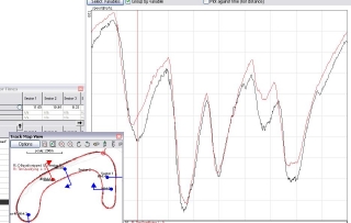
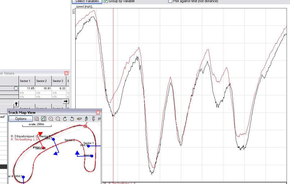
One of the delights of having data-logging is that it's possible to compare your driving with someone else's. In
this case, the someone else is (inevitably) Tim and Adrian, both of whom provided me with their data from qualifying
sessions at Brands. The results are rather interesting - Tim's best lap is a low 52s, Adrian's is a mid 53s, and
mine is a mid 54s. There are various differences between our respective fastest laps, but taking the two extremes
(my fastest qualifying lap and Tim's), it's easy to see where the differences are. The graph shows our respective
speeds at various points in the lap, and starts off at the start/finish line, while we're still accelerating towards
Paddock Hill. The first drop is the braking into Paddock, and the bottom of the dips in the graph are effectively
the circuit's 5 main corners - Paddock, Druids, Graham Hill, Surtees, Maclaren/Clearway.
There's not a great deal of difference between our speeds down into Druids, around Druids and Graham Hill and towards
Surtees. There are three major differences - firstly, I'm braking into Paddock while Tim's already got on the throttle
and is accelerating. Secondly, I'm braking too early and waaaay to hard for Surtees and the entry into Clearway.
Unusually, therefore, I'm doing OK on the slower corners, but totally gibbing out on the fast ones. More brave
pills it is... |
Shiney shiney sumpy - Operation Continence part 4
My modified
sump has never been exactly oil-tight. I don't think it's
actually the welds which aren't oil-tight, merely the sump plug and water/oil pump drain tube recess. With a bit
of work I suspect I could get it oil-tight. However, as I've already mentioned, I'm going for a far blingier alternative
by getting a billet sump made by me ol' mucker Jonathan Rarity aka JB7. Having given the go-ahead to start the
machining after having checked the foam blank and the polycarbonate sheet with the holes in, JB7 sent me the two
billet sumps. Apparently they were a total sod to make, taking up a total of 30 hours machining time - I gather
than the main problem was the depth of the sumps (65mm internal depth) which caused rather a lot of play in the
cutters. Given my experiences of machining deep recesses, like on the rear brake bells on the FuryBirdII,
I can believe that.
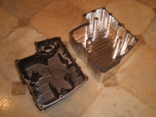
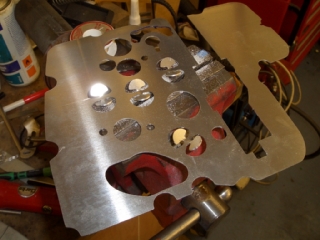
And here's one of the billet sumps, as delivered, alongside a largely-standard factory sump. The billet sumps are
fairly chunky - the bases are 10mm thick, three of side walls are about 13mm deep because I need to put connections
in the sides of the sump - one for the oil-line to and from the external sight glass/air-oil separator, one for
a drain plug, one for a temperature sender, and one for a QR dry-break fitting I'm planning to use to take some
of the messy lack-of-joy from oil changes. However, the largest fittings have a 1/4"NPT thread, so they only
need a thicker section of wall which is, say, 18mm x 18mm square, not an area 75mm x 75mm. So plenty of machining
to do there.
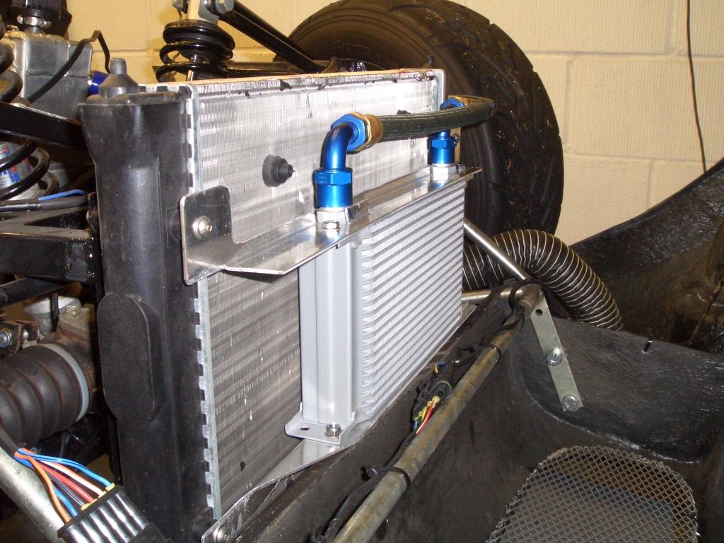
The bases are 10mm thick for two reasons - firstly because you can get aluminium billet off-the-shelf in 75mm (3
inch) thickness, and you can't get 68mm thick plates. Secondly, while fitting
the oil cooler has helped reduce the oil temperatures, with
a consequent knock-on effect on the water temperatures, they're still slightly higher than I'd like. The bottom
of the sump protrudes, just, below the floorpan of the car - although since the steel tow loop at the front of
the chassis does as well, by 8mm, it doesn't restrict how low I can legally run the car without hacking the tow
loop off. The plan is therefore to machine a series of slots into the base, in effect making a row of fins on the
bottom of the sump, in the hope that the sump will therefore act as a more efficient heat exchanger and that the
air passing underneath the car will help cool the oil. |
 |
 |
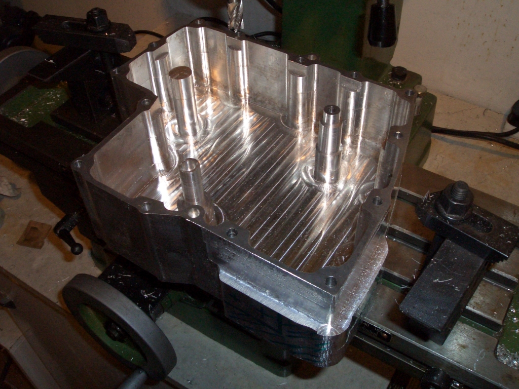
Both the inside and the outside of the billet sump needed machining.
JB7 had spot-drilled where the mounting holes need to go, but had left it to me to drill them. The bolts holding
the sump onto the engine are M6 bolts, but the holes are 7mm diameter. With a centre-drill to drill pilot holes
and a bit of care making sure the 7mm drill bit lined up precisely with the pilot holes, drilling the 7mm mounting
holes was fairly easy. On the factory sump the mounting bolts are accessed through cast recesses in the walls of
the sump - I need to recreate that on the billet sump by machining away a column of material above the bolt hole.
On the factory sump the mounting bosses are 13mm deep, but the deepest I can machine with my existing range of
cutters is 55mm, which means (since the sumps are 75mm deep overall) that the mounting bosses are 20mm deep. Which
means all the M6 caphead bolts I've got are too short. Bugger.
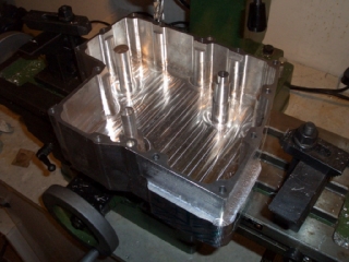
Another bit of internal machining was required on the three columns inside the sump. One is a bolt hole, the second
has a drain tube from the gap between the water and oil pumps (which are both situated inside the engine) going
into it (sealed by an O-ring), and the third is simply a stand-off to sit underneath the part of the baffle plate
which would originally have been held in place by the oil level sensor which I'm not fitting in the billet sumps.
One of the trickier parts of this work was turning down the outside of the bolt hole and drain tube stand offs.
There was quite a lot of excess material, and so I decided that I didn't want to leave them as they were. However,
putting the whole sump in the lathe and using that wasn't really feasible as it's too big. Using my boring head
on the milling machine seemed like a better option, but I don't have any left-handed boring tools - because you're
machining the outside of the workpiece rather than (more conventionally) the inside, the cuting edge on the tool
needs to be on the other side of the tool. The cheapest left-hand boring tool I could find to find the boring head
was over 50 quid, so rather than spending that I just hacked about an existing boring tool on the bench grinder
and turned the backwards face of the cutting tip into a reasonable imitation of the forward face of the cutting
tip. That way I could run the tool backwards, and machine the outside of the columns. Not pretty, but it worked
as long as you took things nice and slowly. |
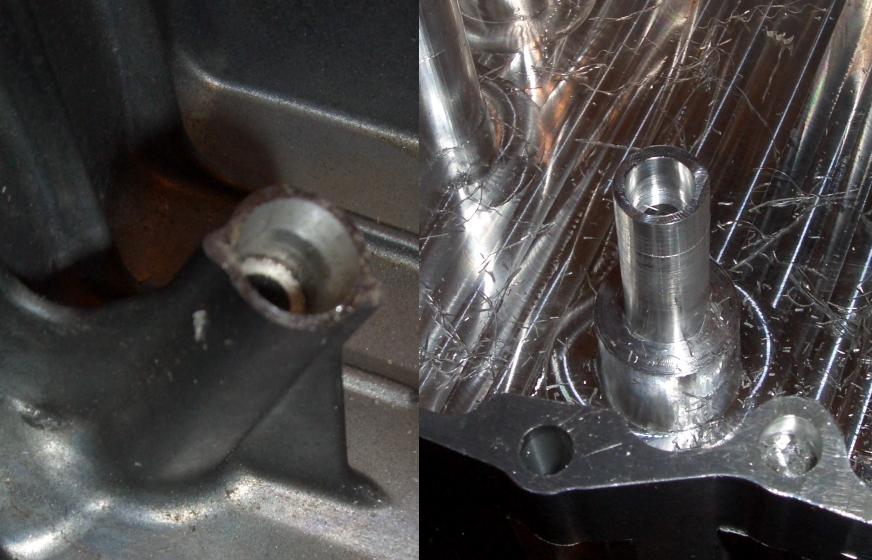
Another moderately tricky bit of machining was the oil drain tube. The
way this works is that there's a tube coming down from the gap between the seals on the water and oil pumps, which
share a common drive shaft running down the middle of both of them. The tube has a flare towards one end, and an
O-ring sits on the end of the flare. The O-ring is then placed in a recess in the sump, which is tapered in order
to help get it in place. Probably easiest to look at the photo (the one on the left is the factory sump) to see
what I mean.
Machining the drain hole, the recess with the shoulder for the O-ring to mount onto, was easy. However, without
using the lathe and the taper-cutting cross-slide, cutting a taper would be more difficult. One option would be
to tilt the head of the milling machine, put the sump on a rotary table, and cut the taper that way. However, the
bed of the milling machine isn't big enough to do that since the sump would clash with the main column of the milling
machine as you tried to turn it all the way round.
So in the end I just got a taper reamer from eBay, chopped the end off with an angle grinder, and used that slowly
with lots of cutting fluid to make the taper. A fine plan, but unfortunately the taper on a taper reamer is, of
course, very slight so that the hole it's being used on can very slowly be opened up. It did produce a taper, but
one so slight as to be almost imperceptible. So I got a small rat-tail file and created a taper by hand, which
is what I should have done all along... |
 |
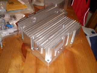 |
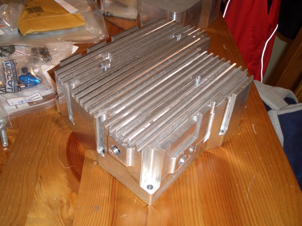
The machining required on the outside of the sump consisted of machining
down the thick walls to provide mounting points for the ports in and out of the sump, machining the recesses for
the bolt holes, and making the fins along the base of the sump. Machining the recesses was reasonably straightforward,
complicated only by the fact that while my longest end mill is 55mm long when mounted in the Pozilock chuck, the
quill of the milling machine doesn't have 55mm of travel so the machining had to be achieved in two bites. Oh,
and the fact that of course a 55mm long 12mm end mill is a wee bit flexible.
Machining the slots in the base was straightforward, but deathly dull. Each slot took about 6 passes, so that's
an awful lot of wheel-spinning. Makes a power feed for the milling table seem like a very attractive option before
I do the spare sump. The final job in machining the outside of the sump was to give the base a quick skim just
to take off the layer of dull metal left on the ends of the fins. Shiny...
The holes in the base are for the additional mounting point, the outlet from the drain tube, and the third is where
I've hollowed out the stand-off marked as number 3 above. The flat section where the fins have been machined away
is the hole for the PRV stand-off, which I've had to install separately. I'm not entirely sure of the details,
but JB7's CNC router forgot to leave the PRV stand-off which the foam version of the sump had. The stand-off is
necessary, since it's the only thing that stops the PRV from flying off into the bottom of the sump by the oil-pressure
behind it. On the factory sump there's a flat section of the bottom of the sump which holds the PRV in place -
you can just about see it on the photo of the factory sump at the top of the page. On the new sump the bottom of
the PRV is about 40mm from the bottom of the sump, so something was needed to hold it in place. Said something
is just a bit of 25mm ali round bar, with a 20mm diameter recess going down to within 5mm of the bottom, a 5mm
base, and 12mm slots milled in the sides. I did take a photo of it in place, but I appear to have lost it. And
I'm not taking the sump off to take another one...
The PRV stand-off is bolted through the bottom of the sump with a countersunk head allen key bolt, and all rendered
oiltight with the use of Loctite 542, which Paul Rogers (RGB's currently winningest driver) recommended to me after
seeing the consequences of one of my many earlier oil leaks. I've used 542 sealant on all of the fitings going
through the walls of the sump, so hopefully they'll prove oil-tight. The fact that they're all NPT taper fittings
and so should seal automatically will hopefully help too. |
Baffle plate
As part of the new sump, JB7 also made me up a couple of new baffle
plates. A new one was necessary because the new sump doesn't have the oil level sender in it, and so the hole cut
in the standard baffle plate for the oil level sender to fit through would have be rather counter-productive. Happily,
while I remembered that the new baffle plates would need to have the oil level sender hole left out, I forgot that
they'd also need another hole left out. On the original sump there's a strange crescent-shaped baffle which extends
above the sump - you can see where I've machined it off on the factory sump in the photo above, along with a much
shorter little ridge of material alongside it.
The new billet sump doesn't have this crescent-shaped vertical baffle (I'm hoping it'll be rendered unnecessary
by the baffle plate itself) and so doesn't need the hole for it - again, having a large and unfilled hole in the
baffle plate would be a bit pointless. On one baffle plate I've tried cutting out a filler piece and welding it
into place. That wasn't a total disaster, but the problem is that there's really not much material around the hole.
For this one, which I've used in the engine (the other one needs a *lot* of filing to get usable after my clumsy
welding) I've taken a rather more straightforward approach and rivetted a filler piece in place. There's plenty
of clearance on both sides, so there's no good reason not to do so, and it's much easier than welding the filler
piece in place. |
 |
 |
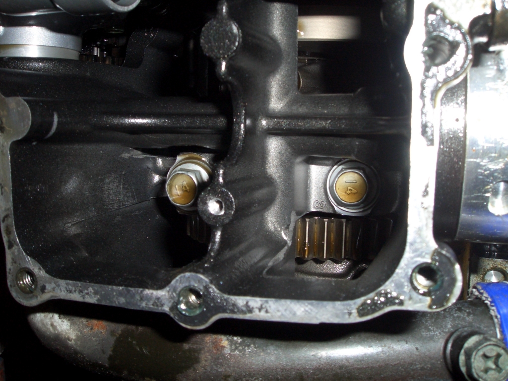
With the standard sump, one side of the baffle plate is held in place by being sandwiched between the oil pipe
which bolts into place, while the other side is held in place predominantly by the oil level sender. This sits
at an angle, so once it's slid into place through the hole in the baffle plate, it keeps the baffle plate located
vertically. However, on the billet sump, no oil level sender = no hole in baffle plate = nothing to hold it in
place. That was the reason for the stand-off shown on the internal picture above - my idea was to have this in
place, with a plastic or rubber bung on top (the baffle plate sits about 10mm above the top of the sump) to hold
the baffle plate in place. However, that would still leave the baffle plate able to wang up, and therefore down,
since there would be nothing above it on the other side of the stand-off to clamp it firmly into place. And since
it's made of fairly thin ali, repeated wanging seemed like a bad thing.
So instead, I screwed my courage to the sticking point, and drilled a hole in the one of the webs of the crankcase,
and tapped it out to M4. Not surprisingly, I found an awful lot of excuses to not do this job... However, once
done, it meant that when I'd replaced all the oil pipes etc. which hold one half of the baffle plate in place,
I could simply bolt the other end into place with a suitably shortened M4 bolt. |
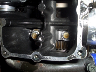
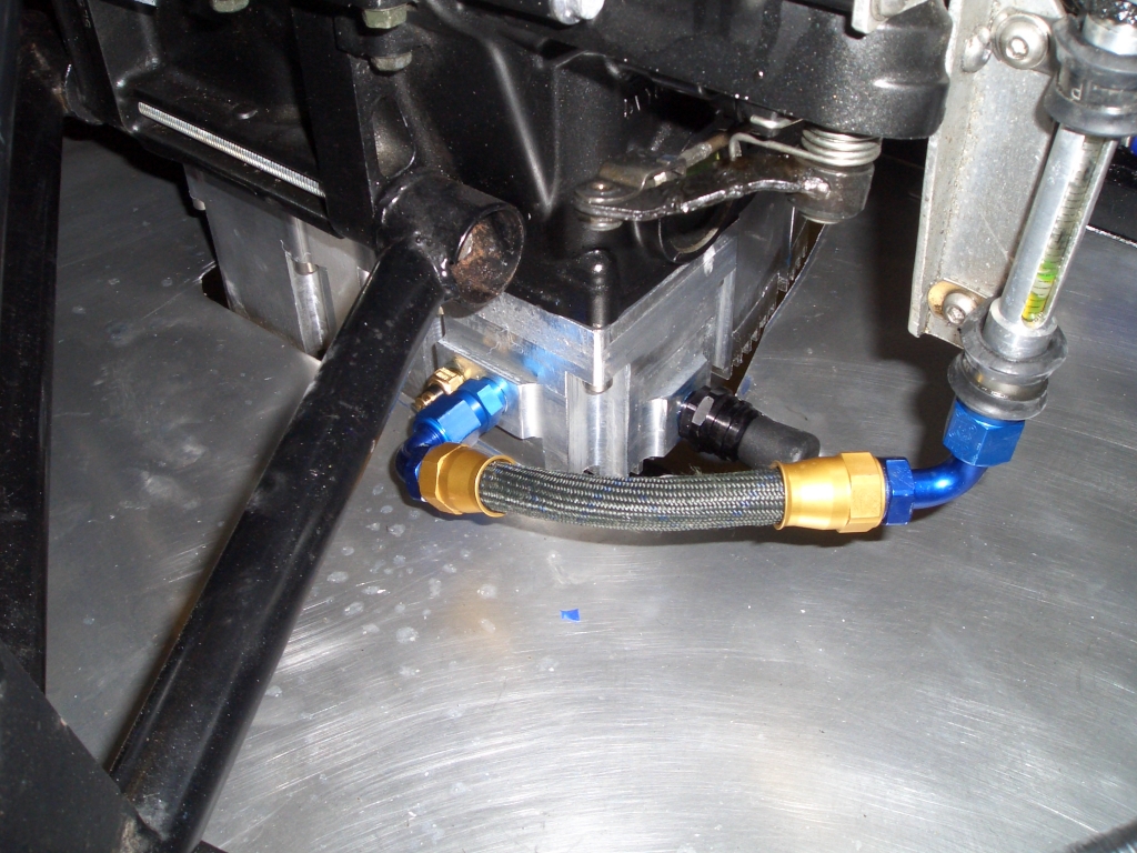
Sump installation
The new sump fitted into place rather nicely. All the bolts lined up, the dowels lined up, and even the drain
tube from the oil and water pump seemed to be seated. The picture shows some of the connections to and from the
sump - there's the QR dry-break connector at the front, with a plastic cap over it to stop muck and grime getting
inside it. There's the -6 JIC adaptor to take the hose from the bottom of the external sight glass, and behind
that you can just see the oil temperature sender. |
 |
 |
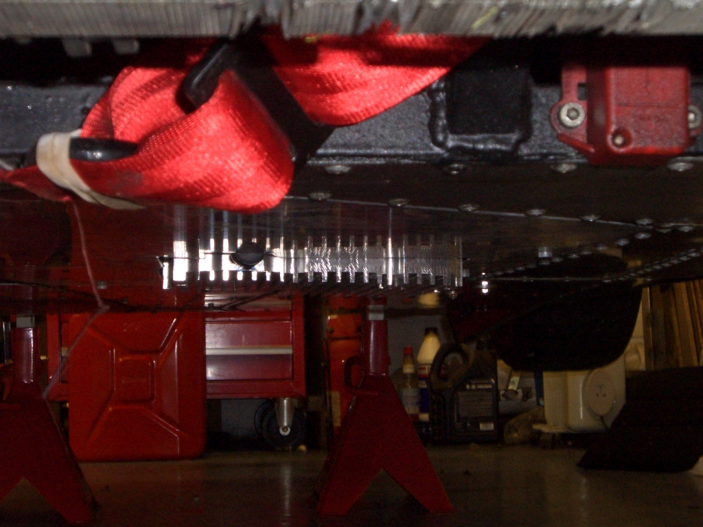
And here's a photo of the underneath of the sump. It's a little bit lower than I'd planned - the idea was that
only the fins would protrude beneat the bottom of the car - but it shouldn't affect the minimum ride height to
any significant extent, and if it does prove troublesome there's probably scope for machining a few mms off the
top of the sump, without overly reducing the clearance between the bottom of the oil pick-up pipe and the bottom
of the sump. |
| The best news was that with 6 litres of Motul synethic oil in it, and
having obtained oil pressure with the plugs out, with the engine running, the sump appears to be oil-tight and
therefore a significant improvement on the previous lash-up. Here's hoping it stays that way. |
|
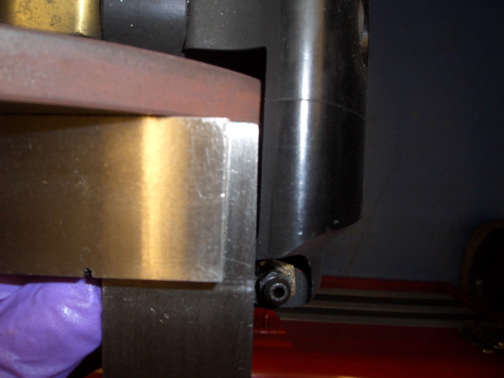
Upright machining
| No, not machining while upright, but the machining of uprights. As a
result of having discovered that the calipers weren't
square to the discs, the obvious answer was to machine the
caliper mounting faces flat after my earlier misguided efforts to do so many years ago with an angle grinder. The
correct tool for the job was also obvious - the milling machine. What was less obvious was how to clamp the workpiece
(i.e. the upright) in place to ensure that the mounting faces would end up parallel with the disc. The key line
is the centre-line or axis of the upright's stub axle, but since this is an axis down a piece of material, it's
a wee bit tricky to clamp it to anything in practice. |
|
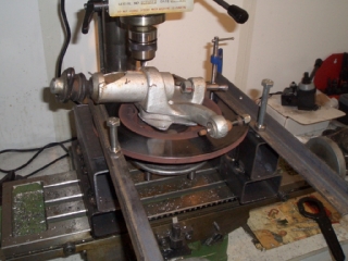
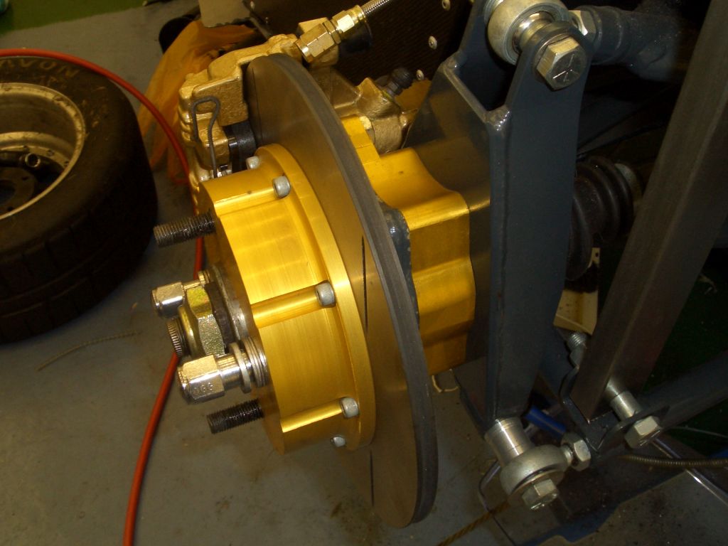
This is the rather Heath Robinson set-up I ended up using to hold the
upright in place. While I couldn't clamp the stub-axle axis, with the wheel bearings rather tighter than normal
I could be reasonably confident that the brake disc was orthogonal to the stub axle axis and that therefore the
caliper mounting faces needed to be parallel with the disc. The mounting blocks are to lengths of 3" x 2"
steel tubing, welded together, and with holes drilled in the bottoms so that they can be attached firmly to the
table of the milling machine (using M12 bolts in the T-slots in the table). I machined the top faces of the mounting
blocks flat using the milling machine, and then clamped the whole lot in place using the strips of angle iron you
can see, held in place at the back with some G-clamps, and then tightened up with some nuts and bolts at the front.
While doing the machining it certainly seemed stable enough, and the amount of material I had to take off showed
that the caliper mounts certainly weren't flat previously. Of course, I've no idea whether this is the real problem
with the front brakes, or whether it is simply that the front left caliper has gone duff for some obscure reason,
but I can't see how everything lined up properly can do any harm.
Oh, and for those wondering how I stopped the whole upright rotating around while I was machining it, I took a
leaf out of Tim's book, and used some zip-ties to hold the steering arm in place... |
 |
I've also discovered why the front left brake disc appears to have rather
a lot of run-out, and I don't think it's anything to do with the discs. Instead, I think it's due to the fact that
when I was fitting the new wheel studs I, erm, inadvertently lamped seven shades of proverbial out of the mounting
faces for the discs on the front left hub. I'd tried filing everything flat, but evidently it wasn't. I've done
a bit more filing, and while it's better it's still not there. Option 1 is to keep filing away until the mounting
face is flat, but that's very dull. The second option is to think of a way of mounting the hub in the lathe and
then turning down the mounting face a smidge to make sure it's true. However, the hub would be far from straightforward
to mount properly. Option 3 is to use this as an excuse to buy some aluminium hubs - at the moment I'm still using
the standard steel Ford ones. The only problem is that as far as I can see the only place to buy aluminium hubs
for standard Escort Mk2 uprights (as opposed to the RS2000/Capri struts) is HiSpec Motorsport, and as usual they're
not bothering to answer e-mails, having better things to do than deal with prospective customers. Maybe I'll have
to see if they can be bothered to pick up the 'phone...
Anyway, that hopefully sorts out both the continence problems and the braking problems. Off to Brands to see if
I can knock a second or so off my best lap-time. |
|


