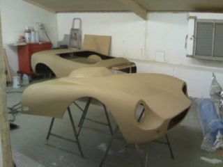
As for the painting, it was the same procedure here as with the sidepods and the scuttle. First, a coat or two of etch primer...
| Having wired everything up, it was time to see if the engine would start
from the dash controls. FIA switch on, and the DL1 lights up as it should do (I've followed Tim's advice and wired
the DL1 in on a permanent +ve line, so it's only switched by the FIA switch and not the ignition switch. Ignition
key switch on, and the warning lights and DASH2 come on (as you can see above), but the fuel pump doesn't prime
(which it should). And the engine wouldn't start. Bugger. I started off trying to work out why the fuel pump wasn't priming properly, which I assumed (incorrectly) was due to a fault in the fuel pump wiring circuit. When I'd formerly got the engine running the fuel pump wiring was a total lash-up, whereas I'd now wired it properly through the dash switch (the left-side toggle switch with the red emergency cover to the right of the FIA switch cuts power to the fuel pump). It turns out, of course, that it was nothing to do with the wiring for the fuel pump. However, in investigating the fault, including rather destructively taking apart the relay/diode pack which contains the fuel pump relay and starter circuit interlock relay, I did learn a few things. 1. Haynes manuals obviously just copy the factory service manual wire diagrams. The service manual shows a resistor in the relay/diode pack, albeit one which according to the diagram isn't actually connected to anything. There is no such resistor - just lots of diodes, 2 relays and a zener diode. Which Mr. Haynes would know if he'd taken apart the diode pack rather than just copying Mr. Yamaha's diagram... 2. There's an error in the Yamaha service manual for checking the fuel pump relay works. There are two blue/yellow wires coming out of the diode/relay pack. One is the earth sink for the fuel pump relay, the other is the earth sink for the interlock relay. The diagram in the Yamaha service manual shows the wrong blue/yellow wire as being the sink for the fuel pump relay - it should be the other one (and they're not internally connected - I checked). 3. The relays for the fuel pump and starter circuit interlocks are tiny. Roughly 8mm x 4mm x 5mm. And yet can handle 40A. Jolly clever these Japanese chappies. In the end the problem turned out to be the tip-over sensor, or rather its absence. I'd rather fancied keeping the tip-over sensor - after all, shutting the engine down if the car turns upside down seems like a jolly sensible idea to me. However, the problem with these is that they're generally based on pendulums (pendula?) which when mounted in a car get tripped every time you go round a corner fast because (once again) bikes lean over in corners whereas cars don't. I was convinced that the Yamaha tip-over sensor couldn't be large enough for a pendulum-based device, but I was wrong again. It contains a tiny pendulum with a magnet on it and some circuitry (Hall effect sensor) mounted in this small box. In order to work out how to bypass the tip-over sensor I back-probed the sensor. It showed impedances of 1.8 million ohms for one side of the circuit and 155k ohms for the other side. Based upon a supply voltage of roughly 12 volts this gave an output for a potential divider with R2 as 155k ohms and R1 as 1M8 ohms of about 1 volt, which is apparently what the ECU expects to see when the bike is upright. So to fool the ECU into thinking the tip-over sensor was present and working properly, I added 1M8 and 155k resistors between the signal wire and the +ve supply and earth wire respectively. There were 2 problems with this otherwise incredibly cunning plan: 1. The +ve line isn't 12V - it's 5V. The ECU generates a 5V line which is distributed throughout all the blue cables in the engine loom. Presumably the sensors need a regulated voltage to work consistently, and 5V is easier to generate than 12V. 2. I suspect the tip-over sensor contains active circuitry rather than just working as a passive potential divider. Also, I suspect that by using resistors with impedance as high as 1M8, the internal impedance of the ECU was having an effect on the voltage being created by the potential divider. At any rate, if I left the signal wire unconnected to the ECU it gave a voltage of about 0.4V. Once I connected the signal wire to the ECU this went up to over 4V. This was, of course, why the engine wasn't working and the fuel pump wasn't firing - the ECU thought the bike was lying on its side. I reduced the value of the R2 resistor in the potential divider all the way down to 1k2 ohms before I got an output voltage in the correct region (just over 1V). As soon as the voltage from the tip-over sensor bypass circuitry got into the right range, the fuel pump primed and the engine started with no difficulties. It took 8 hours to get this sorted, and sadly none of it was very photogenic... |