12th December 2008

Dashboard

  The dashboard is now in place, even if the lower edge is still held in place by Clecos. I had been planning to have the dashboard sit in front of the rear edge of the scuttle, but I think having it behind the edge of the scuttle should make the rear of the dashpanel are bit more weatherproof.

The dash is held in place by 4 ali panels running between it and the scuttle firewall. It's reasonably rigid with all 4 of the ali panels in place.

Fitting the dashboard meant I could finally refit the steering column and gear shift and linkage. This meant I could make and fit...

...some Firewall blanking plates

The firewall between the engine bay and the cockpit is, as the name suggests, intended to provide a degree of fire protection for the cockpit in the event that everything inside the engine bay starts getting a bit toasty.

In fact, the MSA Blue Book require any firewall to be of a solid fire-resistant material. My view is that fibreglass, a material renowned for burning fiercely once it catches fire, isn't the obvious choice for such a structure, but the scrutes don't seem to mind and frankly I don't care. What the scrutes do seem to care about is miniscule gaps in the highly flammable firewall - hence these plates to fill in the holes around the steering column and gear linkage rod.

Using a brake master cylinder gaiter as a gaiter for the shift linkage is yet another cunning idea I've blatantly nicked off
Tim...
 

Foam seat

  The choice of seat for the Furyracer was simple - proper racecars have foam seats. For one thing, this will hopefully prevent me from suffering the same injuries as I did in my last big shunt, where the lack of any side support from my seat meant I just smashed into the transmission tunnel. So, something with a bit more lumbar support was going to be required.

In theory making a foam seat is easy - get a couple of heavy duty bin bags, tape them together to form an extra-long bin bag, lob a load of 2-part PU expanding foam in there, sit on it, and wait.

And here's me testing out that theory, sitting in a bin-bag full of warm expanding foam. Photographic credits to SWMBO, who observed that in her opinion we wouldn't be needing much foam to fill in the gaps between me and the cockpit sides...

This picture is actually of attempt number 2 in progress. Attempt number 1 was a bit of a disaster. We did in fact run out of the foam I'd bought, so I pitched some more of, yep, Tim. I mixed some of the foam from Tim, judging the quantity based on how the stuff I'd bought had expanded. However, it seems that Tim's garage is substantially warmer than mine, as it expanded considerably more rapidly than the stuff which had been cooling gently in my garage for a few weeks.

In fact, it became a choice between getting out and letting the whole thing congeal into a big ball of foam, or risking the distinct possibility that the bags would burst under the pressure and leave me encased in the car, covered in foam. Discretion being, in this case, the better part of valour I took the first option.

Hence, the need to start all over again. This time I took things fairly slowly - this is after the first 'pour' and it's really just a flat base for a seat.
 

  This is after the second pour, and using some rather larger if flimsier bin bags. You can see that the edges of seat now go much further up, to provide a bit more support. I reckon one more lot of foam to get the sides of the seat in place around the upper torso and it'll be time to start covering it. I've decided to cover the foam seat in GRP rather than tank tape - opinions are varied (me versus everyone else) as to whether this is a good idea or a worthwhile use of time, but we shall see...

25th December 2008

Brake pressure sensor manifolds

A chap on eBay was selling some rather nice pressure transducers, rated to anything up to 300 bar, and with a burst pressure of over 1000 bar. Just the thing for logging brake line pressure, and at 25 quid each, including the connector, pretty reasonably priced too.

However, the thread on the end are 7/16" UNF and seal using an O-ring. 2 obvious problems - standard brake-line fittings are designed to seal to SAE O-ring face sealing fittings, and secondly, the O-rings the senders came with were buna rubber, and so not compatible with brake fluid.

The latter problem I solved by buying some EPDM O-rings to replace the rubber ones, although due to the industry 
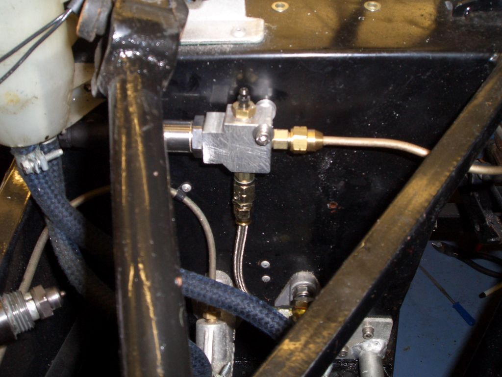
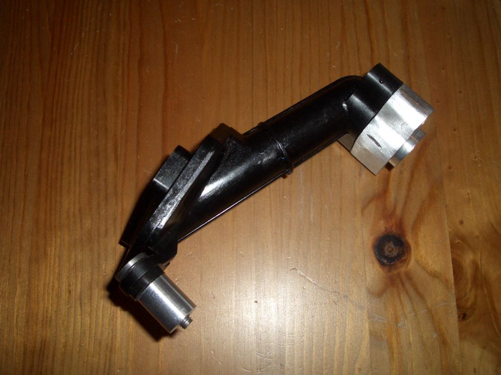
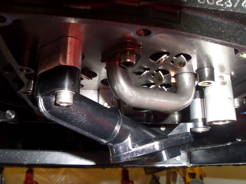
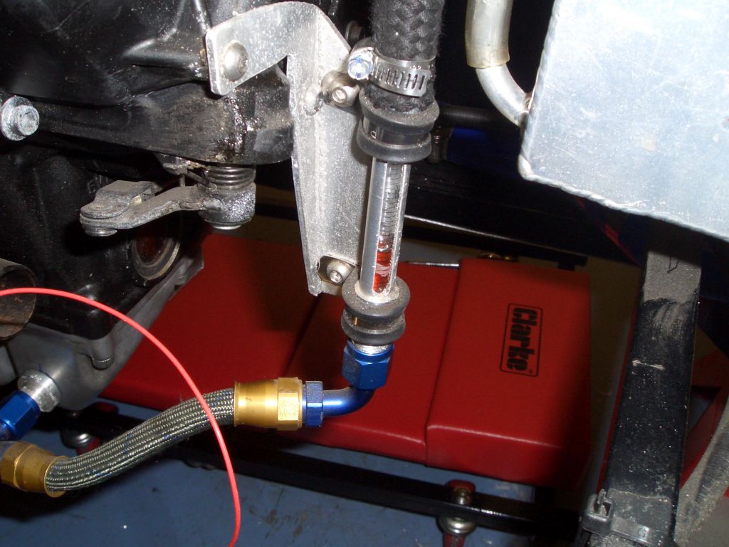
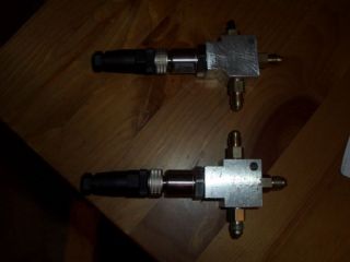
standard minimum order quantity of ten quid, I now have 72 spare. To solve the connection problem, I've made up these little manifolds from ali blocks. The sender hole has a 7/16" thread, and the other threads are 1/8" NPT with 1/8" NPT to M10x1 adaptors fitted.
 

  This is the manifold for the rear brake line in place. There's a bleed nipple in the top to bleed the manifold, and because the manifold is so close to the master cylinder I've used a short length of flexi hose rather than brake pipe to connect the manifold to the master cylinder.

The reason for adding the sensors is two-fold - firstly, it allows me to log braking force rather more accurately than just having a line from the brake switch, and secondly it should allow me to set the brake bias rather more accurately. One of the problems with brake bias adjusters is being able to return them to an earlier setting, and with the brake line pressures displayed in real time on the DASH2 I'm hoping I'll be able to do that fairly easily.

More sump modification work

A wee snagglette on the on the sump modification front. The sump has recesses where the sump bolts go into the crankcase to allow access to the bolt head. One of the main reasons for modifying the sump was to lower the oil pick-up pipe, which is the black thing in the foreground of the picture. However, as you can see the end of the pick-up pipe is very close to one of the bolt holes, and by lowering it, the edge of the pick-up clashes with the inside of the recess referred to above.

However, with a lot of careful measurement it seemed as though there was enough meat in the pick-up pipe to allow me to relieve it enough to clear the recess in the sump. So, I pressed ahead and made up...
 

  ...these spacers to drop the oil pick-up pipe by 19mm. There were quite a few clearance issues, most particularly around the third mounting point on the left-hand side of the photo. There's very little space between the bottom of the sump and the end of the bolt/spacer combination to hold this part of the pipe in place.

And here's the oil pick-up pipe in place with its spacers. With everything in place, it was time to refit the sump. This was an amazingly fiddly job, not least because while the hole in the sump baffle for the oil level sender is in the correct position to accommodation the oil level sender when the sump is in place. However, the level sender is at an angle to the sump, so the hole isn't in the right place when you're putting the sump into position. And having the oil pick-up pipe 19mm lower does limit one's room for manoeuvre.

After about an hour and a half of fannying around, the sump was in place. So I connected up the hoses, filled it with oil, and stood back in satisfaction. And then noticed the steady drip, drip, drip of oil from the bottom of the sump pan...

Arse.
 

  The leak was from the hole for the drain tube which runs from the cavity between the oil and water pumps, and means you can tell if the seals on either have gone. During the endless attempts to fit the sump I obviously lost one of the O-rings which goes on either end of the link tube, and this meant that the tube wasn't sealing properly.

To solve it properly would involve undoing the hoses, dropping the sump, taking off the pick-up pipe, taking off the other pipes beneath the baffle plate, dropping the baffle plate, relieving the hole for the oil level sender, replacing everything and reinstalling the sump with new O-rings for the link pipe.

Instead, I tapped the hole which was leaking and put a bolt up inside it - you can just see the button-head of the bolt I used. I'll put fixing it properly on my list of things to do for next winter's off-season fettling...

31st December 2008

Engine ignition in T-10 (hours) - air filter

Starting the engine had become long overdue, so I've set about doing the jobs I need (or at least ought) to do before trying to start the engine for the first time. I planned to start the engine using a fairly virgin bike loom, molested as little as possible, to check that there was nothing fundamentally wrong with the setup, and before hacking the bike loom apart to incorporate it into the car's electrics generally.

One job which needed to be done was to fit the air filter to the air box. In the absence of anywhere else to put it, I've put the air filter in the sidepod. Hopefully the air in the sidepod will be slightly cooler than the air in the engine bay generally. To connect the two I've got some 81mm flexi hose, but the neck on the air filter is 81mm and the hose is remarkably unwilling to stretch. So, first job was welding a slightly narrower extension onto the air filter neck. And here it is. While still moderately poxy, I suspect this is the best bit of DIY ali welding that will be on the car - ironically it'll be underneath a layer of gaffer tape when it's in the car.
 

  The air filter sits in the sidepod and is connected to the airbox via the flexi hose. It'll be held in place by a stay mounted to the top of the chassis once I've got the bonnet back from the spray booth and I can see where it's best to run it.

It's not the most elegant solution in the world, but in the absence of a custom airbox there's not really much of an option about where to stick the filter. While a custom airbox would be nice, and I may get round to doing it eventually, it's not a priority for now.

Engine ignition in T-10 (hours) - fuel filler

Starting the engine also involved having a working fuel system. First thing to do was to fit the supports for the fuel filler which I'd fabricated earlier and had powder-coated.

Next in the list of things to do were filling the tank, test running the fuel pump, blurting petrol all over the floor when the pressurised air in the feed and return lines hit the fuel tank and expanded, cleaning the floor of all the spilt petrol, and claiming that this job was done.

Oh, and I also fitted the one-way tip-over valve in the breather line, with the fuel line itself suitably grommeted into place.

Happily, none of the 14 or so joints in the fuel system seem to have leaked. Yet.
 

Engine ignition in T-10 (hours) - cooling system

  The cooling system was another of those jobs which technically didn't need to be finished before the engine start (it's done but remains unfilled to date) but it seemed to make sense to do so before starting the engine.

On the bottom left is one of the main water pipes, with a small bit of welding to take the water temperature sensor and a hole tapped for an earthing strap, and on the top right is the expansion tank with the minor water pipes going to it. The reason for the extensive length of silicone hose is to allow me to lift up the expansion tank when filling the cooling system - the top of the cooling system on the engine is only just below the top of the expansion tank and I think I'll need the extra height to bleed it properly.


Engine ignition in T-10 (hours) - oil system

Having spent so long on the modified sump, there wasn't much to do here other than fill the engine up. As you can see, the external sight glass has worked fairly well, albeit at this rather early stage, making the oil level pleasingly easy to identify.

The external sight glass also acts as the return line for the air/oil separator...
 

  ... which is now properly mounted with some brackets to mount it to the catch tank, and the catch tank now has the K&N crankcase breather on top rather than just having some holes drilled in the top.

Time will tell whether this set-up will prevent the edge from spitting its oil out as soon as it's driven hard. If it does, then it may be necessary to add a breather line from the cylinder head and into the air/oil separator. But I'd rather not do that unless it's really necessary.


Engine ignition in T-10 (hours) - battery

The last pre-ignition job was to fit the battery, which I have ended up placing in the highly inconvenient position I'd thought of earlier, wedged firmly between the side-panel in the engine bay, the master cylinders and the engine mount. It's also held in place by some ali angle rivetted into place, and two straps made from the customary 1" ali strip and 3mm self-adhesive foam rubber strips.  

Engine ignition in T-10 (hours) - final preparations

  Then all that was necessary was to do a bit of jury wiring - cobbling the fuel pump to the bike's fuel pump relay, twisting various wires in the bike loom together, and reducing the controls on the bike loom to 1 button and 1 switch - the switch turned on the ignition, and the button started it.

I hooked up the bike loom to my jump start box (the large yellow box balancing precariously on the chassis), and wired up the oil pressure sender/low pressure switch to a multimeter so I could check the oil pressure. It seemed to take ages to get oil pressure (at least sufficient to make the low pressure switch go off) but it turned out that the switch only turns off at 1.25 bar, and according to the pressure sender I was getting just under 1 bar on cranking the engine, hence the switch staying on.

The engine didn't start first time - I'd left a few wires unconnected which needed to be connected, the plugs were fouled and needed to be changed, and once I'd done all that the jump start box went flat so I had to connect everything up to the newly-fitted and charged battery.

On the 8th attempt, however, the engine burbled into life.

So now it's a question of taking apart the jury-rigged wiring, taking the bike loom apart and splicing the bike loom into the dashboard room and the (as yet unmade) 'rest of the loom' loom. Can't wait.