23rd October 2008

Dashboard assembly

  After having finished the pods for the dashboard I could fit it all together with the DASH2, and the 3 lamps directly in front of the driver. The 3 lamps are for neutral (lots of green LEDs in a cluster), brake fluid/handbrake warning light (standard small filament lamp, with the correct markings on for SVA), and the oil pressure warning light (lots of red LEDs in a cluster).

The holes left unfilled in the right hand switch pod are for the indicator switch and the dipped/main beam switch - I've got to decide which ones to get for these, but either way they'll be toggle switches.

Now I've just got to wire up the dashboard (ooo, can't wait) and attach all the resulting wires to a 40-way multipole circular collector I've got for it to connect to an equivalent plug mounted on the scuttle.

Wheel speed sensors

As part of the 'weighing the job up' process of pre-wiring deliberations (i.e. putting off actually starting doing it) I noticed that the DL1 has 4 inputs for frequency inputs, not including the rpm input. One of these will be for the speedo (although the DASH2 will have to have its own input for SVA purposes as otherwise the odometer won't work) but that leaves three remaining channels. 4 wheels, 4 channels... Hhhmmm...

After a bit of humming and hawing about whether logging wheel speed independently for each wheel was worthwhile, i decided I may as well give it a go. I got 4
1GT101DC gear tooth Hall Effect sensors from RS components - they're the same ones Race Technology sell, but RS do them for 17 quid each rather than RT's 30 quid. They need a pull-up resistor to be fitted in order to connect them to the DL1, which Race Technology fit to the ones they sell, but a 1k resistor's only a couple of pence.

I was expecting fitting the sensors on the rear wheel to be rather tricky but actually it was pretty straightforward. The sensor picks up on the heads of the wheel studs (there is a gap between them, although less than a mm) and the whole thing's mounted on the mounting brackets for the rear calipers. The disc covers the sensor when it's in place.
 

  The sensors on the front wheels detect the bolt heads holding the brake discs onto the back of the hubs. There's not all that much space to play with given the PCD of the bolts and the bulk of the upright. For this reason it's not possible to get the bolt head and the head of the sensor quite in line, but I'm hoping a sufficient quantity of bolt head will wander its way past the head of the sensor for the sensor to notice its presence.

The ali bracket for the sensor is held onto the upright using the threaded holes which would previously have held the the dust shield for the front brakes onto the upright. They have M10 threads, and using M10 bolts to hold a sensor in place seemed a bit excessive, so I drilled holes down the middle of the button-head bolts. Well, with a lathe it's a 10 second job, so why not?

Fitting the sensors was a bit of a faff, since fitting the bracket and the sensor meant taking the hub and disc off, which meant I couldn't check the clearance between the sensor and the bolt head until I'd refitted the hub and disc. And if it wasn't quite right, that meant taking it all off again, to adjust the spacer between the sensor and the mounting plate.
 

Sump mods - continued

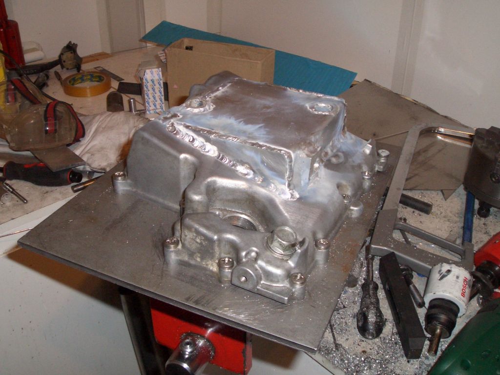
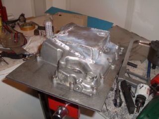
  I've also been doing more work on the modifications to the sump pan. Having chopped a large hole in the bottom of the sump, I've almost finished welding the extension plate on. As you can see, I've extended the tubes for the mounting bolt and the oil/water pump drain. I'm not convinced the latter's going to be oil-tight - I couldn't quite weld all the way round the base of the extension tube as there wasn't enough space to get the TIG torch in there - but I can always sleeve it if not.

I've mounted the sump onto a 6mm thick piece of steel before starting the welding. Although the sump's a reasonably thick piece of casting, my TIG welding 'technique' on ali still involves pumping a vast amount of heat into the workpiece, and I didn't want it to warp. The welds are a bit rough, but they should be plenty strong enough and with a bit of luck they'll even be oil-tight too. Naturally, I'll make sure the sump's water-tight before I fit it.

You can also see the boss I've welded on the side of the extension - the standard sump plug (right on the corner of the sump closest to the camera) is a bit useless on the modified sump.

Once I've finished the sump, I've just got to work out a way of extending the oil pick-up down by an inch and a bit. Which will be a bit of a swine, I suspect, as I've now remembered the pick-up pipe is plastic, and even with TIG I can't weld plastic...

Wiring - stripping the bike loom

The wiring on the Furyracer involves three tasks - stripping and cutting down the bike loom, making up the rest of the loom, and then connecting the two together. This is the first EFI build I've done, and the EFI loom is considerably more involved than one for a carb'd engine. There are a whole host of sensors, and the ECU seems to have meglomaniac tendencies - I can see why it might consider it necessary to control the fuel pump (and bork if it can't) but quite why it needs to control the headlights (which are on all the time anyway) is rather beyond me.

Anyway, I've connected the engine up to the bike loom, and I've stripped the bike loom of all the tape and goo holding it together. I did start working out which bits to chop off and which bits to leave, but I've decided (given the complexity of the loom) to start the engine first before chopping any of it off. So I've starting concentrating on stuff I need to do to get the engine running.
 

Fuel filler mounting

One thing I need to do to get the engine running is to finish off the fuel supply. This involves filling the tank with petrol, which will be a lot easier if the fuel filler's in place. On most Furies, the fuel filler is mounted onto the rear bodywork, and connected to the fuel tank(which sits below the top chassis rails) by a length of fuel filler hose. I can't do this on the FuryRacer for three reasons:


1. There's no point going to the trouble of making a pivotting rear tub and then attaching the tub firmly to the chassis with a length of fuel filler hose

2. When I had my big shunt at Mallory the fuel filler got ripped out of the hose connecting it to the tank, with the result that I got covered by the contents of the petrol tank while sitting underneath the car after it had rolled. As a result, the 750 Motor Club introduced a rule meaning you couldn't bolt the fuel filler onto the bodywork.

3. It's a good rule, and bolting the fuel filler cap to the flexible bodywork which is prone to move quite a lot in a crash is A Bloody Stupid Idea.

  So intead of being bolted to the bodyshell, the fuel filler (black flush-fitting aerospace unit, natch, complete with SVA-compliant unleaded fuel restrictor) is attached to this bent of bent ali...

...which is in turn attached to the chassis/internal panels with this rather elaborate network of ali panels complete with big holes. The idea is that the fuel filler is held rigidly in place so that...  


  ... when the rear tub swings down, the head of the fuel filler fits into a hole in the rear deck of the main tub, but in an accident, if the rear tub moves sideways the fuel filler will stay where it is and the tub will simply slide over the top of it.

No doubt the SVA tester will say it's not secured sufficiently, while the scrutes will say it's too securely fastened to the bodyshell, but I'm perfectly happy with it. The ali panels are off with some other stuff I've made recently being powder-coated - once they're back and fitted and can test the fuel pump and see if the fuel system is continent.