25th March 2008

More work on the sidepods

  With the bodywork in place, albeit held there largely with gaffer tape, I could fix the sidepods in place. The sidepods are held in place with aluminium brackets rivetted to the chassis rails and the aluminium panels on the chassis, and a small strip of ali angle joining the front end of the main tub to the top of the side pod.

I've also added a few bolts through the floorpan extensions (where the ali floorpan panel extends beyond the side of the chassis) up into the sidepod.

While I made all the brackets up I used Cleco panel pins to keep everything locked in place. They're great tools, and invaluable for this sort of work.

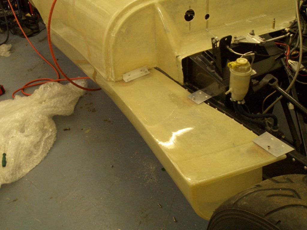
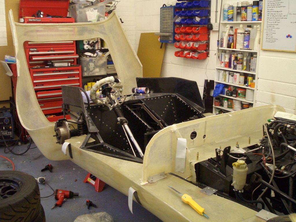
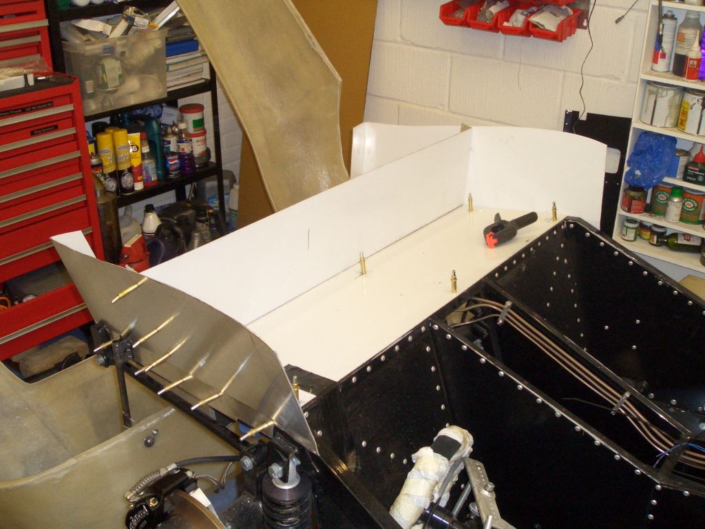
Once all the brackets were made up and the holes drilled, I attached the aluminium brackets using the usual combination of PU adhesive and pop rivets. The sidepods need to be detachable, 
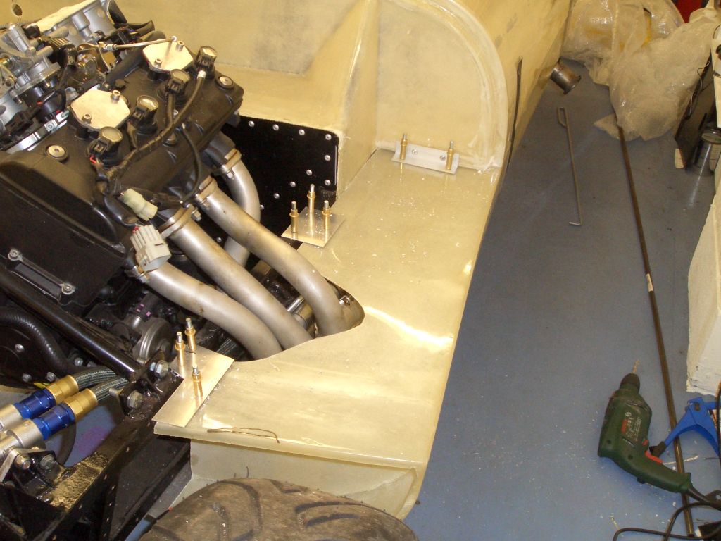
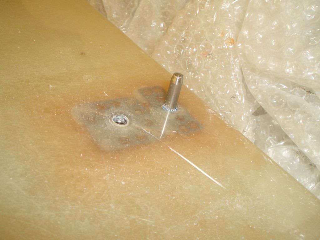
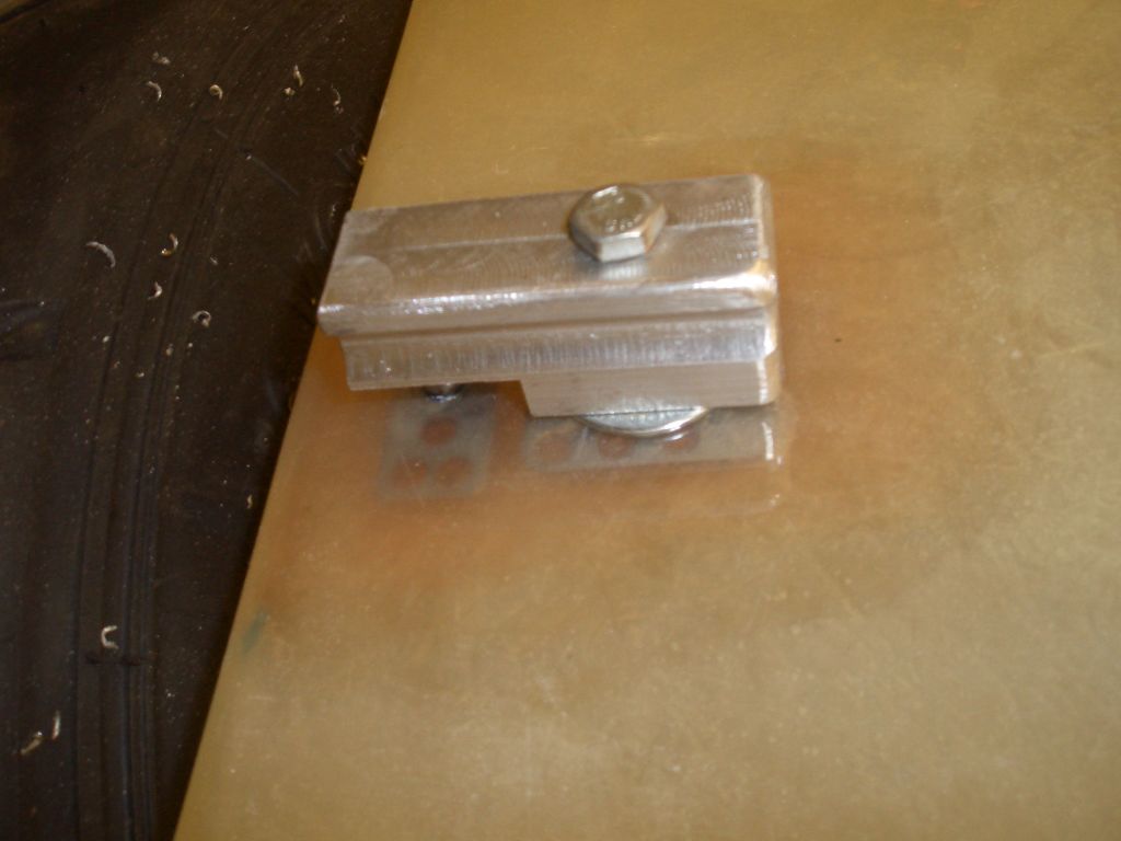
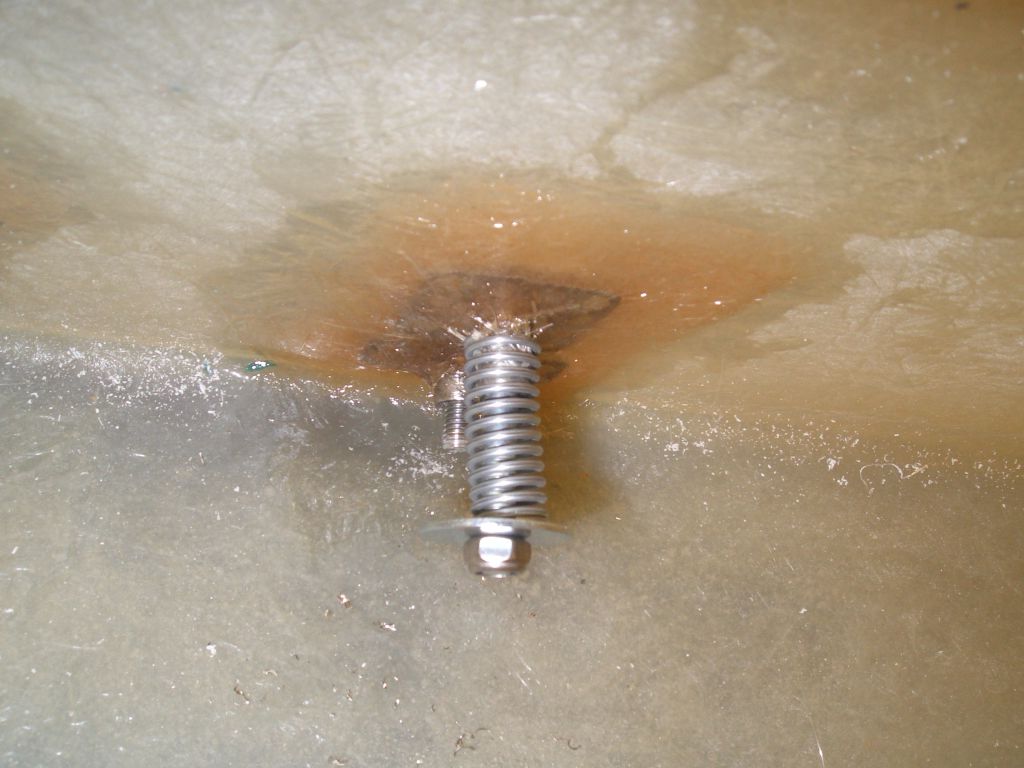
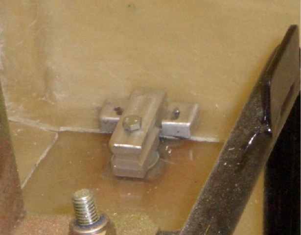
and so pop-rivetting them in place wouldn't be a great idea. Instead, they're bolted into place using Bighead M6 fasteners bonded into place with some GRP and polyester resin.

The Bighead fasteners appear to work really well and provide a very secure way of adding captive nuts in GRP. In fact, I managed to cross-thread one and the stainless bolt sheared before the Bighead fastener came adrift.

They're not the lightest way of adding captive nuts, admittedly. Aluminium rivnuts would be lighter, but I used them on the Furybird I, and half of them pulled through even before I spanked the car into the Armco.
 

Rear tub pivots

  As with the Furybird II, I want the rear tub to be detachable from the sidepods but rather than having to lift it out of the way (an enormous faff IMHO) I'd rather have it pivot in a similar manner to the bonnet. The obvious pivot point is the bottom of the rear tub, just behind the rear wheels.

This means an extra bit of chassis for the rear tub to pivot from, and some ali brackets on the rear tub.

The bit of steel tubing from which the rear tub will pivot needs to be spaced out slightly from the 2" chassis rail, as otherwise it would clash with the leading arm underneath it - the leading arm protrudes very slightly.

In this picture everything's just resting in place, ready to be attached rather more firmly...

...such as welding the upper support in place. At the moment it's just tack-welded in place - I'll wait until I've removed the rear tub before welding it fully, as I don't particularly want to set fire to the rear tub.  

And then...

  ...work ground to a half again as I went skiing again. Two feet of fresh powder in Verbier - could be worse.

31st March 2008

Back to work - more bodywork...

With the sidepods bolted into place and the front of the rear tub attached to the chassis (using Clecos) and the sidepods (using bolts and the Bighead fasteners I'd fitted) I could separate the majority rear tub (which is going to swivel up and out of the way on the pivots pictured above) and the scuttle (which isn't, as it's got the steering column going through it for one thing...).

I did this with a padsaw (which is resting on the sidepod in the photo) - boring, hard work, but more control than I'd have using either a hacksaw or the air powered saw. Created an immense amount of GRP dust too - RIP garage vacuum cleaner...

With the rear tub separated from the scuttle, I could see if the pivots for the rear tub work - as you can see, they do.
 

Internal main tub catches

  Because of the way I've separated the scuttle from the main tub, the bonnet will hold the front of the main tub down. But of course it wouldn't be sensible to rely purely on that, so I need some way of attaching the sides of the main tub to the sidepods. The usual way of doing this is to put over-centre catches on the front and rear of the mating face between the main tub and the sidepods.

This can cause a problem for SVA as there's only one truly SVA friendly over-centre catch I know of, and it's a really-not-a-thing-of-beauty-and-a-joy-for-ever big lump of rubber and IME they don't really work that well.

Instead, I'm making my own catches that will go inside the tub. Having drilled some holes and bonded in even more Bighead fasteners in the inside of the sidepod, the first thing was to make up and fit the locating pins. These are made from M6 stainless bolts I've turned down in the lathe. They fit into holes drilled in the return flange on the sides of the main tub and keep it in the correct position both laterally and longitudinally.

With the locating pins keeping the rear tub in the right position, all that's needed is something to keep it there. I've made up 4 aluminium clamps like the one in the photo - these were machined from billet on the mill. Ultimately they'll be held in place by a caphead bolt, the head of which will be recessed into the top of the catch, rather than the hexhead bolt in the picture.

I've still got to finish off bevelling the edges of all the catches - I've made a start on this one, but it's a boring job which really has to be done by hand (in the absence of a CNC mill). For SVA purposes, however, I need to put a 2.5mm radius on all the exposed edges of the catches.

The left hand side of the catch (as viewed in the photo) has a 6mm hole drilled in the underside so that the top of the locating pin goes inside it (you can just about see the bottom of the locating pin in the photo).
 

  The catches need to be sprung in order to apply a clamping force between the sidepod and the main tub. This is how I've achieved it - this is a view of the underneath of the catch shown above.

The M6 bolt holding in place goes through an M6 Bighead fastener which I've drilled out to provide a smooth tube inside. The spring happily just fits over the (formerly) threaded part of the Bighead fastener, and the purpose of the penny washer and nut is pretty obvious. When I rebuild the catches (I'll have to take them off to paint the sidepods and to replace the bolts with capheads) I think I'll make some little ali inserts to keep the spring centred on the bolt so that it doesn't get squashed to one side as it has in the photo.

So in operation the main tub swings down on its pivots. After only a little shoving and pushing, the main tub is in the correct place and the locating pins go through the little plate shown in this picture (they're bolted to the sidepods with M4 CSK SS machine screws and bonded in place with metallised epoxy as well). The end of the locating pin sticks through the top of the plate by another 5mm, and the plate has a recess in the middle for the catch to sit in.

Once the locating pins are through the holes in the main tub plates, it's a simply job of lifting up the catches, turning them round so that the hole in the underside of the catch lines up with the locating pin, and dropping them into place.

I was concerned that the springs wouldn't be stiff enough to keep the main tub securely in place, but initial impressions are that it's pretty effective.


Internal panels

  Next job - internal panels. Obviously it's necessary to have something between the chassis and the main tub at the rear, if only to keep the wheels separate from the passenger compartment and in order to provide a fire-proof bulkhead between me and the fuel tank.

Unwilling to break the habit of a lifetime, I'll copying
Tim in this respect. The earlier pictures have the standard Fisher black GRP panel here but 1) it doesn't fit 2) it's really badly laid up 3) the edges of the mould are shot 4) did I mention it doesn't fit?

Making up the interior panels is just a case of making templates, bending the panels where necessary, and then holding everything together with Clecos. All these panels will be powder-coated as well, so I'm not rivetting them into place for now. The ones in the picture still need trimming (there are some pointy edges and the rear end of the side panels catches on the rear tub when it pivots on its hinges) but we're getting there.


But before I did too much more work on the panels it occurred to me that I ought to get the roll cage in place - firstly to make sure that the rear tub clears the front roll hoop when you lift it up, and secondly to see if the aluminium panels around the rear wheels would need fettling to make them fit around the side impact protection bar on the cage.

Answers were yes to both.

I'm a bit concerned about the cage, however - it looks awfully low and flat. I'll have to make sure I'm sitting *really* low in the car...

At some point I'm going to have to drill it and the chassis and bolt it in place as some of the internal panels are going to be sandwiched between it and the chassis. Need to finish the panels first though.