21st February 2008

Exhaust manifold

  There's been a bit of a pause in the build, but not this time due to me getting distracted and doing other things. Instead, it's because the car's been with Competition Fabrications in Norfolk to have its exhaust manifold made.

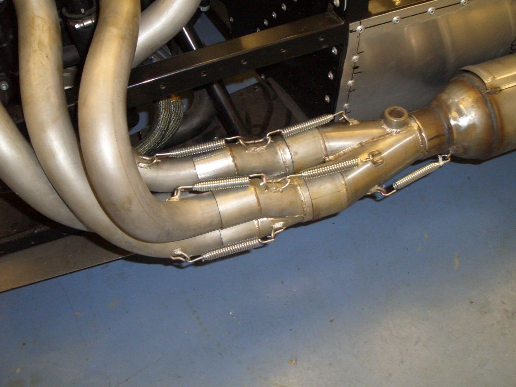
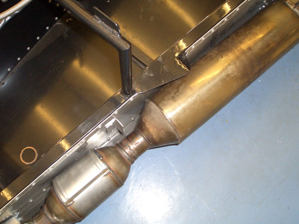
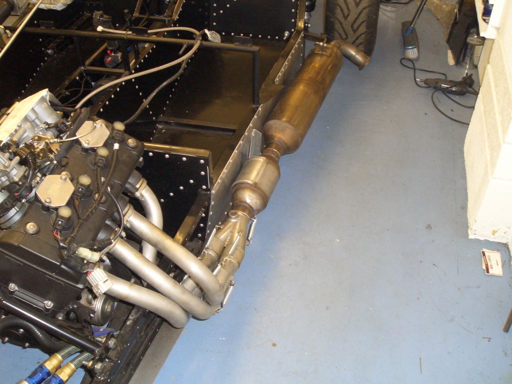
And it's now done, and here it is. It's a stainless 4-2-1 system to a slightly unusual design (at my request) which I'm keeping under my hat for now so that if it turns out to be rubbish I can think of a vaguely credible excuse...

As usual with Competition Fabriactions, however, the quality of the workmanship is very high and all in all I'm very happy with it - although I'll have to see how well it works in practice.

The collectors are all held together with spring fittings with slip joints between them. There is a reason for this - I want to put the car through SVA, for which it'll need the catalytic converter. However, once it's through SVA (and registered on a Q plate) I'll never need to fit the cat again.

Because all the joints are slip fittings, I can remove the cat, seperate the 4-2 and the 2-1 collectors, and fit secondaries between the collectors. And it also means I can change the pairings of the cylinders in the 4-2-1 arrangement which may come in handy if my slightly novel design doesn't work as intended (there's a clue as to why it's slightly unusual).
 

  The only slight issue with the manifold at present is that because it's been made nice and compact to ensure it fits inside the Fury side pod there's very little space between the front edge of the exhaust can, and the cat, and the side of the car. It's not a problem at the moment, but in the event that (post SVA) I decide to use the space liberated by removing the cat not only in introducing the secondaries but also to fit a longer and wider exhaust can it might be.

However, I can easily solve this by having the secondaries kinked slightly to move the front of the car further out. And if the exhaust can is quiet enough to pass SVA it may be fine even if I want to do track days with more restrictive noise limits - we'll see.

Bodywork

Taking advantage of the day off work required to pick up the FuryRacer from Competition Fabrications, I also picked up the two sets of Fury bodywork I'd ordered - one set for the racer and one set for the Furybird II. I haven't had a chance to have a decent look at it yet, so I'm not sure whether it's up (or down) to the usual standards. It's in a clear gelcoat as both cars are going to be sprayed, and both sets are the lightweight race bodywork.

This means it's now time to fill the garage (but hopefully not my lungs) with lots unpleasant GRP dust...
 

29th February 2008

Main tub

  The first job to do was to fettle the rear tub so that it would fit in place, albeit loosely at first. The involved cutting away the inside returns which sit above the sidepods and relieving the edges to provide space for the side impact protection on the driver's side.

At this point the back of the tub is being held up by nothing more permanent than a couple of Tescos cardboard wine carriers...

The next stage was to roughly fit the bonnet in place. This isn't actually fitting the bonnet - just putting it in place so that I can check that the side pods are in a reasonable position so as to provide sufficient clearance for the front and rear wheels. Of course, the fact that neither the rear tub or the bonnet are symmetric makes the whole thing a lot more exciting that it would otherwise be.

You can just about see something sticking through the bonnet - I've already had to cut a hole in it to allow the stepper motor for the second set of throttle butterflies (which are controlled by the ECU) to poke through.
 

Side pods


  With the bonnet roughly in place I could start teeing up the correct position for the side pods. The driver's side sidepod needed a few cutaways - one for the trailing arm and the mount for the trailing arm, and another for the side impact protection on the driver's side. With all that done, I could put it into place and hold it there using some lengths of gaffer tape onto the main tub.

One of the first things I noticed was the fairly epic gap between the top of the sidepod and the main tub, no matter how hard I pulled the lengths of gaffer tape.

Upon a not very intensive inspection the answer as to why this gap existed was rather obvious, and (a recurring theme I suspect) related to the poor quality of the bodywork.

The underside of the main tub had fairly sizeable lumps of resin on its underside, with the inevitable result that the sidepod (the top of which was flat) couldn't sit flush against the bottom of the main tub. This was the one which had the most significant effect (to give you some idea of scale, the larger blob of resin isabout 2 inches long)...
 

  ... while the next potential blob of doom is here - you can judge the scale from the width of the 2 inch gaffer tape.

So the main tub had to come off again, pay a lengthy visit to the back garden, and had to be attacked vigorously with an electric drill with a flap wheel attached. Cue huge quantities of GRP dust.

Once I'd removed the blobs of resin the sidepods fitted much better. You probably can't see it in this photo, but the sidepod is much closer to the main tub. One thing I did notice with everything in place was that there really wasn't much clearance or margin for error around the rear wheels.  

Rear wheels clearance

  There's certainly not much wheel arch spare - as you can see, the wheels and tyres do fill the rear wheel arches fairly comprehensively. In fact, given that I'm planning to SVA the car this could become something of an issue, although at present it looks as though it will be *just* OK.

I'll have to take off the returns on the wheel arches, but according to
Tim, this is entirely normal for a racer with the lowered suspension. As you can see from the picture the airsaw is getting a fair bit of use, and it'll get some more use removing the air saws.
As well as clearance laterally, there's the related issue of clearance around the wheel itself. Because the sides of the wheel arch are mostly inside the outer edge of the tyre, the clearance is limited as when the wheel moves upwards it won't simply move upwards into the wheel arch, as it would with normal cars - if there's not enough clearance the tyre will rub against the bodywork.

Also visible from this photo is the large quantities of filler glommed into the wheel arch returns because the laminators can't be bothered to consolidate the glass and resin properly, and the wrinkles in the gelcoat because the Fury bodywork mould is well and truly banjoed...
 

  The bodywork fits best and with the most clearance if the shell is moved forwards quite a long way. However, with the shell in its 'normal' position there's little scope to move it forwards as the rear of the tub is pretty close to the rear face of the tyre.

The bodywork is the lightweight bodywork and so the rear tub isn't stiff enough to support itself - the back end just sags downwards, further limiting the clearance between the rear face of the tyre and the botton of the main tub.

The rear tub is supposed to be held in place with the black GRP boot floor visible in this picture (which I've already hacked around to make it fit around the fuel filler hose). The trouble is (apart from the fact that it's a really, really, spectacularly nasty piece of GRP, even by Fury bodywork standards) that it's not really tall enough. It's around 16cm high, before it's trimmed to match the curvature on the inside of the tub.

And it could really do with being more like 19cm to 20cm high, as if the rear end of the main tub is pushed upwards a little, then...
 

  ... there's more clearance around the rear end of the tyre and it should be possible to move the rear tub forwards a little, and as a result providing sufficient clearance for the rear wheels and tyres.

Pushing the rear tub up this far means binning the GRP boot floor (no great hardship there) and making replacement aluminium panels (a faff, but it can't be helped).

It also means the sidepod gets lifted off the aluminium floor panel, but this can be resolved by putting Bighead fasteners in the sidepods and bolting them down onto the floor pan.

I've done none of this yet, however, as I've been far too busy...

...skiing with cam7.  

New wishbones

  And yes, I had already made wishbones for this car. And the wishbones I'd already made fitted perfectly on the Furybird II (unlike the Fisher wishbones made specifically for that car, which didn't). But the wishbones were too short for the (allegedly identical) front suspension on the FuryRacer - in order to get 2 degrees negative camber at the car's operating ride height required the rod ends at either end to be wound out to the point where there was rather a lot of thread showing. The inevitable result would have been bent rod-ends, so new wishbones were necessary.

Taking advantage of this I added pick-ups for the front ARB I've decided to add - the picture on the left is of the little jig I made up for the ARB pick-ups.

And here are the first two finished wishbones. I made four in total of this batch - two to fit, and two spares. Normally I'd be tempted to make only one spare, but these are handed due to the ARB mounts, so I need spares for each side.

They'll go off to be powder-coated along with the next batch of stuff - I'll wait until I've got a few more panels that need doing before sending the next lot off.

Hopefully they'll be the last wishbones I make for a while - I think 8 a year is enough...
 

Reverse gear lever

  The last part of the reverse mechanism to do (other than the wiring) was the reverse lever. The reverse mechanism is cable operated, so the lever has a bike brake cable going through it, and you can just about make out the cable stop I've added to the chassis upright at the side of the transmission tunnel.

The lever is another left-over from the Furybird - it's the only bit of carbon on the car (so far). The only mod I had to do to make it fit in the FuryRacer was to turn the right hand home-made pillow-block bearing round the other way and to make the aluminium dog-leg so the lever would clear the propshaft. The dog leg's machined from aluminium and has a slot clamp holding the upper part of the lever in place - for SVA I can remove it and fit something more SVA friendly.

However, for the rest of the time (much to the disgust of the GF) the reverse mech will be topped proudly by a joystick lever. And yes, the electric reverse does work by pressing the trigger on the joystick lever...

So now, I'm nearly in a position to finally fit the transmission tunnel side panels. I think I'll test the reverse mechanism properly under load first though...