![]()
| With the rough edges of the top half of the airbox taken off, it was possible to mount it in place (it mounts onto the base of the OEM airbox using the aluminium adaptor plate I'd made earlier) which meant in turn that I could check that it fitted underneath the bonnet with a reasonable amount of clearance. Given that it's impossible to see up into the gap between the top of the airbox and the bottom of the bonnet bulge once the bonnet is down, I did this using the tried and trusted method of putting blobs of BluTack on the top and seeing how much they got squashed down. Not much was, happily, the answer which meant that it was time to start work on the bottom half of the airbox. | 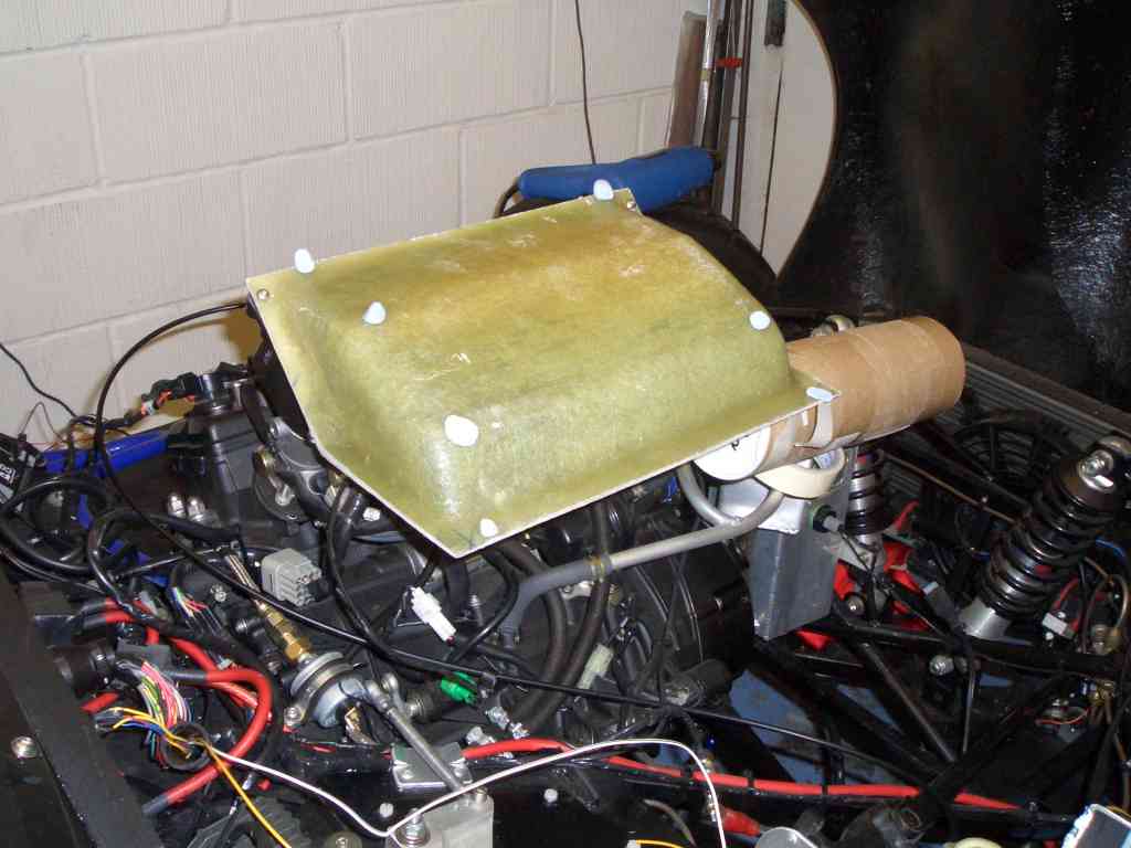 |
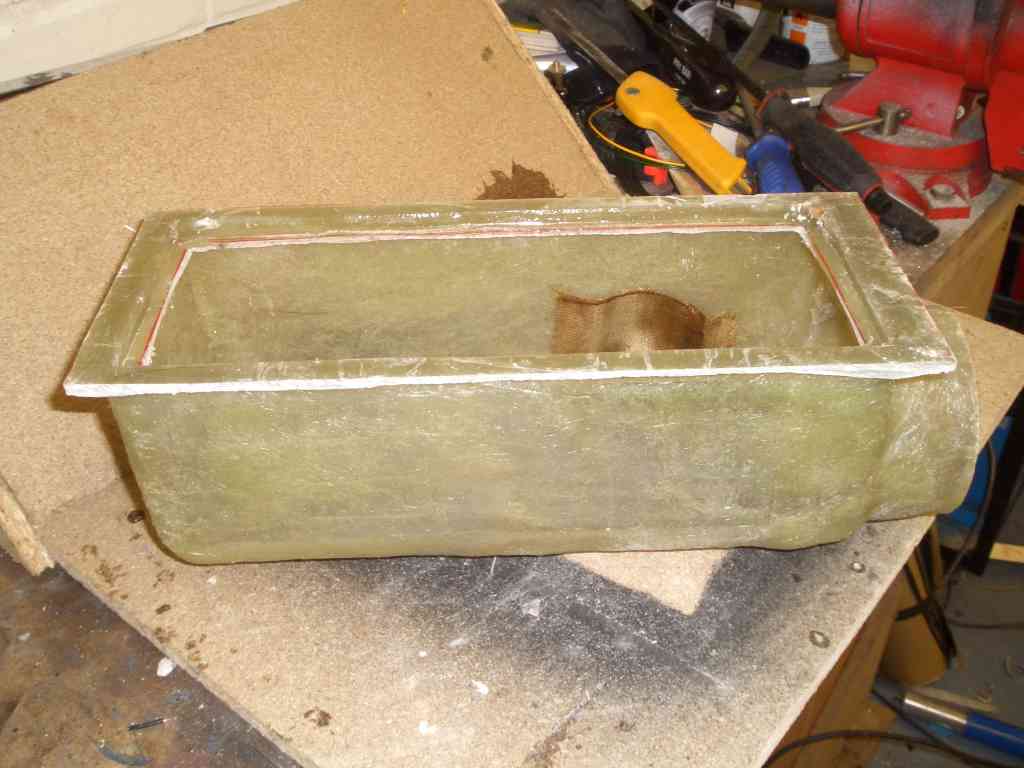 |
WThe process was the same as with the top half of the airbox - a rough
shape hewn from polyurethane panels covered in packing tape and then covered in GRP. The only difference here
was that in order to get the return in the top plate (that's the recess which the inlet side of the panel filter
fits into) I first laid up some GRP over a mid of 6mm MDF which was the same size as the panel filter, and then
laid up the rest of the airbox on top of the resulting flange. The darker bit of fabric you can see inside the airbox is a little Kevlar patch - the airbox was slightly deeper than I'd planned and was hitting one of the fuel lines where it ran over the top of the water thermostat, so a little recess was necessary to give sufficient space for the fuel line to do its stuff unobstructed. The only reason the patch is made from Kevlar is because I left 2kg of CSM on the train by accident, so ran out... |
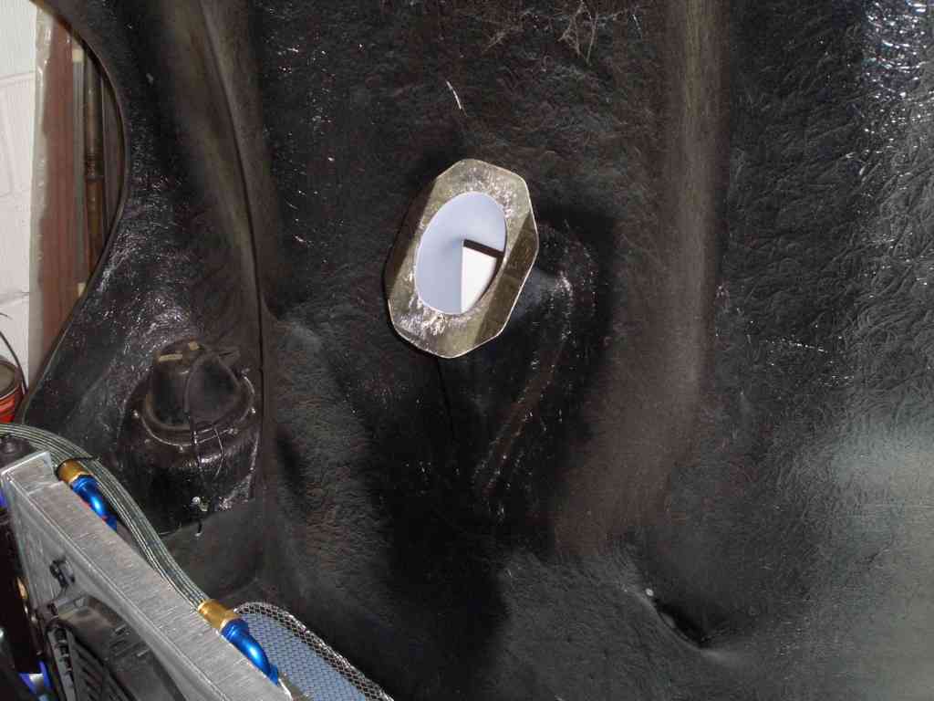
| With the panel filter in place and the two halves of the airbox clamped together, this is how it looks. You can clearly see the recess for the fuel line, and the panel filter wedged firmly into place between the two halves of the airbox. Oh, and the fact that as usual I've sprayed it black... | 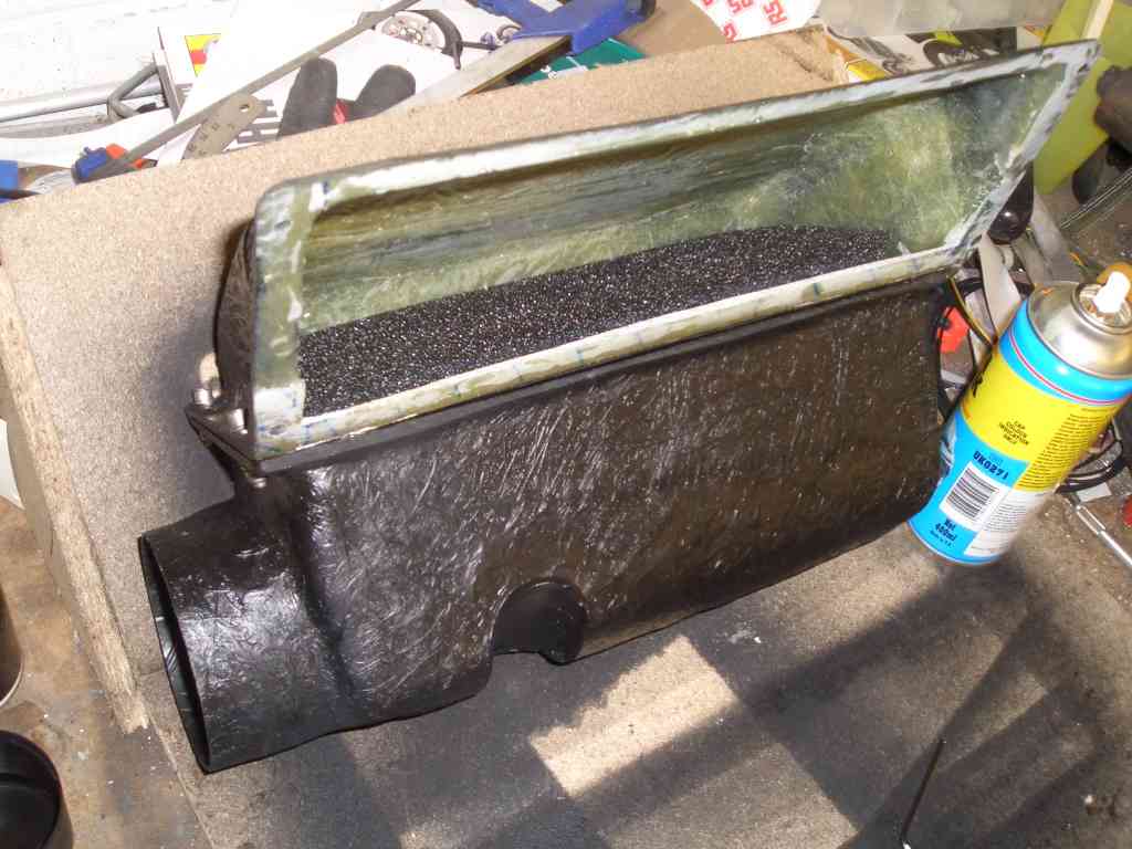 |
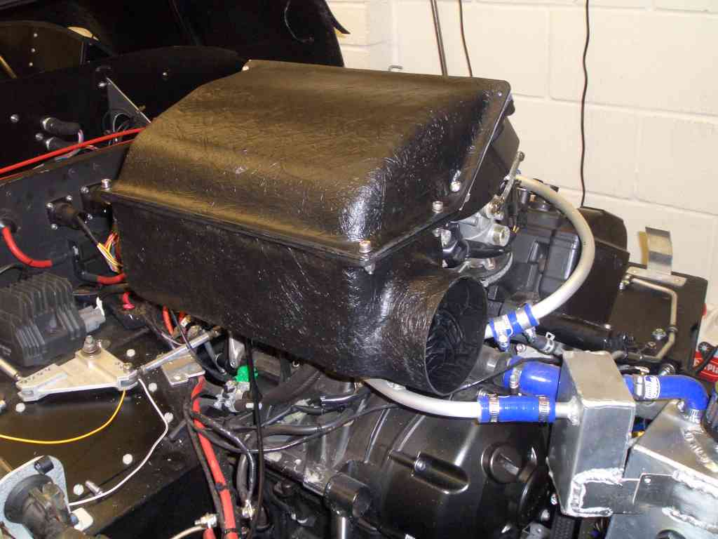 |
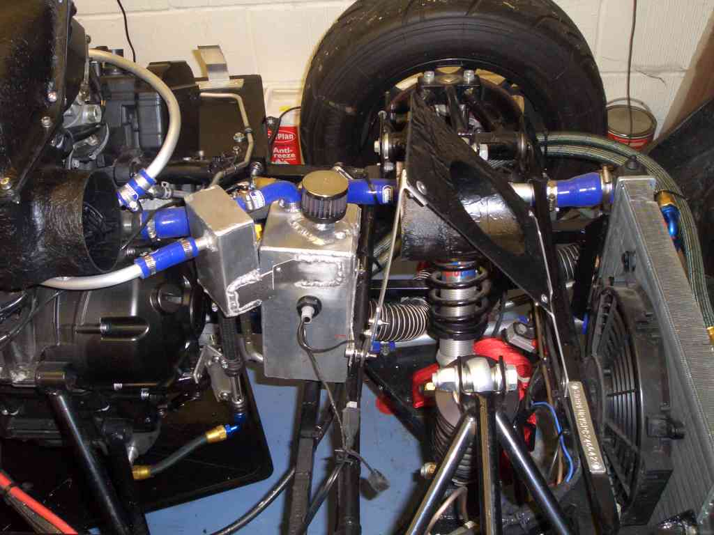
And a quick pic of it in situ. The air/oil separator was completely in the way of the inlet duct into the airbox, and at one point I was anticipating the unjoyful job of having to make up a new catch tank in order to get it low enough to give a straight run from the air inlet in the bonnet into the airbox. With a bit of judicious tweaking I've managed to get it low enough so that the ducting won't have to make too serpentine a path from the NACA duct in the bonnet to the airbox, but I suspect that ultimately I will end up making a new catch tank so that I can get the air duct from the NACA duct to the airbox as straight as possible. |
| I've also got round to fitting the NACA duct. It's the usual Andy Bates version used by every man and his dog in RGB, and has a 100mm outlet. Because I've fitted it (like everyone else) on the underneath of the front part of the bonnet bulge it didn't quite lie flush against the underside bonnet, but with a bit of trimming and a bit of filling it's OK. Obviously I'll need to give the bonnet a quick once-over with some matt black paint, but I'm waiting until I've added the second set of Aerocatches in the bonnet before doing that so I can do all the painting in one go. | 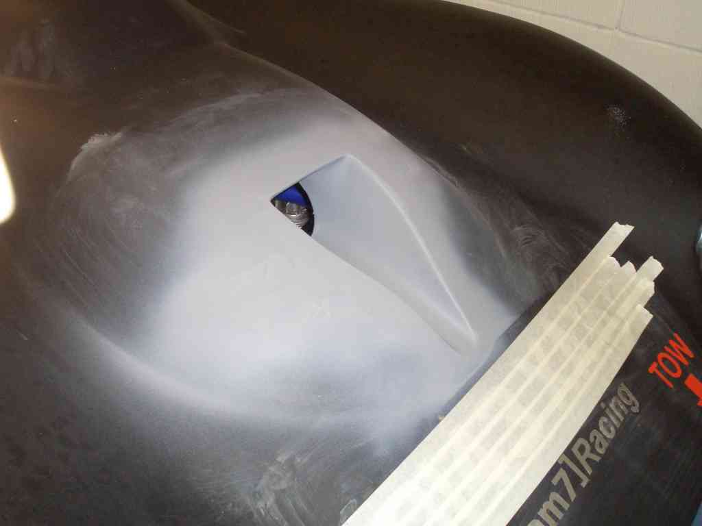 |
 |
This is the underside of the NACA duct where I've bonded it onto the underside of the bonnet with (as usual) some CSM and polyester resin. You can see I've also added a return onto the end of the NACA duct at a roughly 45 degree angle to the airflow. This is so that the NACA duct can be permanently attached to the bonnet, with the air hose leading to the airbox being connected not to the NACA duct itself... |
| ...but to a 'pipe with flange' section mounted to the chassis. Pictures
are, as ever, worth many many words - it's the bit in the picture to the right dangling precariously above the
chassis on some aluminium stays. Now all I need to do (other than taking the whole thing apart and drilling drain holes, holes for barometric sensors etc.) is add the 102mm air ducting between the two, and that's the airbox finished. |
 |
 |
I've also been making further progress on the video camera system. When trying to work out how to mount the camera, without paying through the nose for some of the quite hideously expensive machined billet mounts on there, I came up with this arrangement. The black anodised aluminium mount is an extra-long mount for a Longacre internal mirror, and the camera's held in place with a rubber bobbin from RS, and a machined and fabricated aluminium mount I made. |
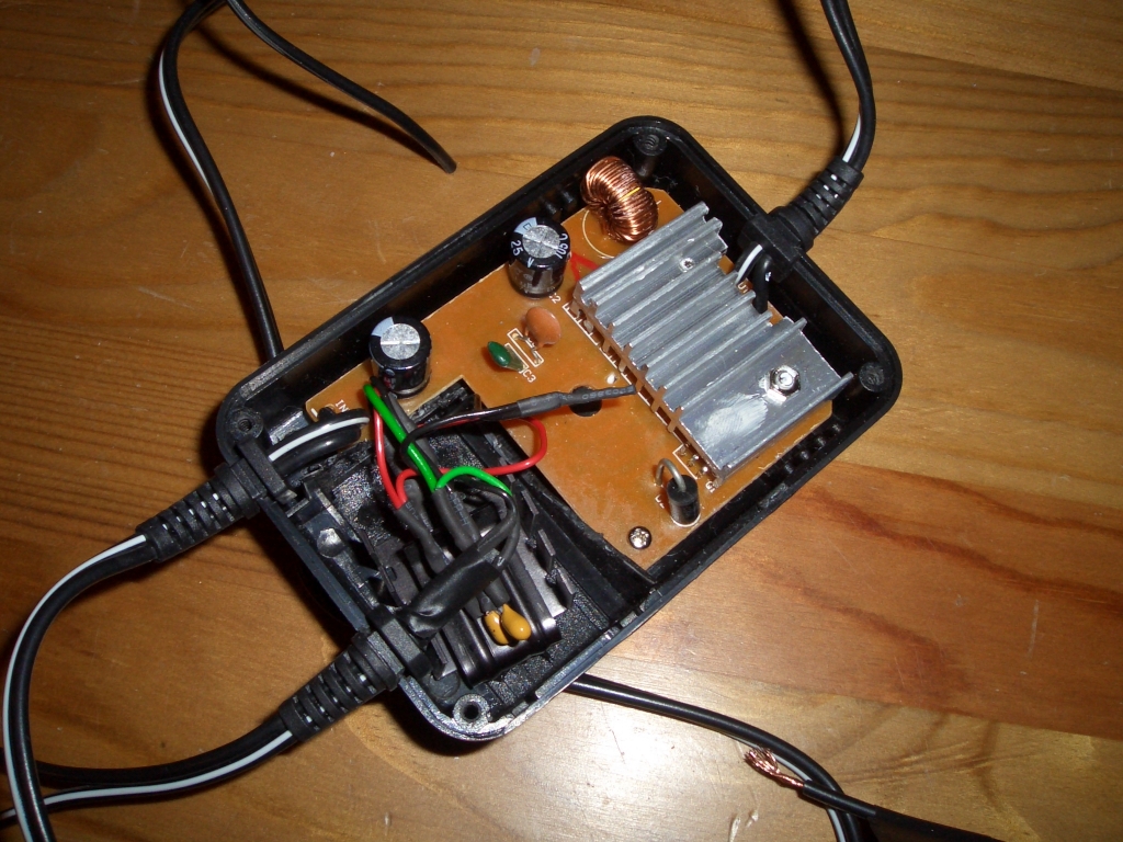
| As for the other end of the system, this is all now wired in and the Neuros and its remote safely ensconsed in a Tesco's Value tupperwaresque locking lid lunchbox. Unfortunately when I first tried to power up the system, not a lot happened. This was, I suspect, a result of me having wired up my bodged-together power supply incorrectly. Really quite amazingly incorrectly to be honest, given that I'd mixed up the input and the output which meant that my Neuros II, designed to have 5V gently massaged into it, ended up having a rather unexpectedly vigorous 12V shoved up its silicon backside. Net result, one gently fried Neuros, and a quick eBay session on me to get another one shipped over from the good ol' US of A. Ah well, an early downpayment on this year's stupidity tax bill... | 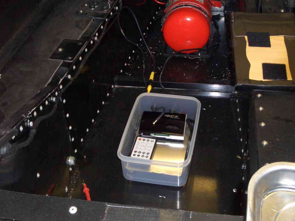 |