30th September 2007

Actually, I got hardly anything done in my week off (well, not on the FuryRacer anyway) but what little I did do (and did during the rest of the month) is here at last.

Chassis cross-brace

  The original plan for the FuryRacer was to simply slap the majority of the mechanical components left over from the demise of the Furybird onto a new chassis, lob a bodyshell on top, and go racing. Naturally, it hasn't happened like that.

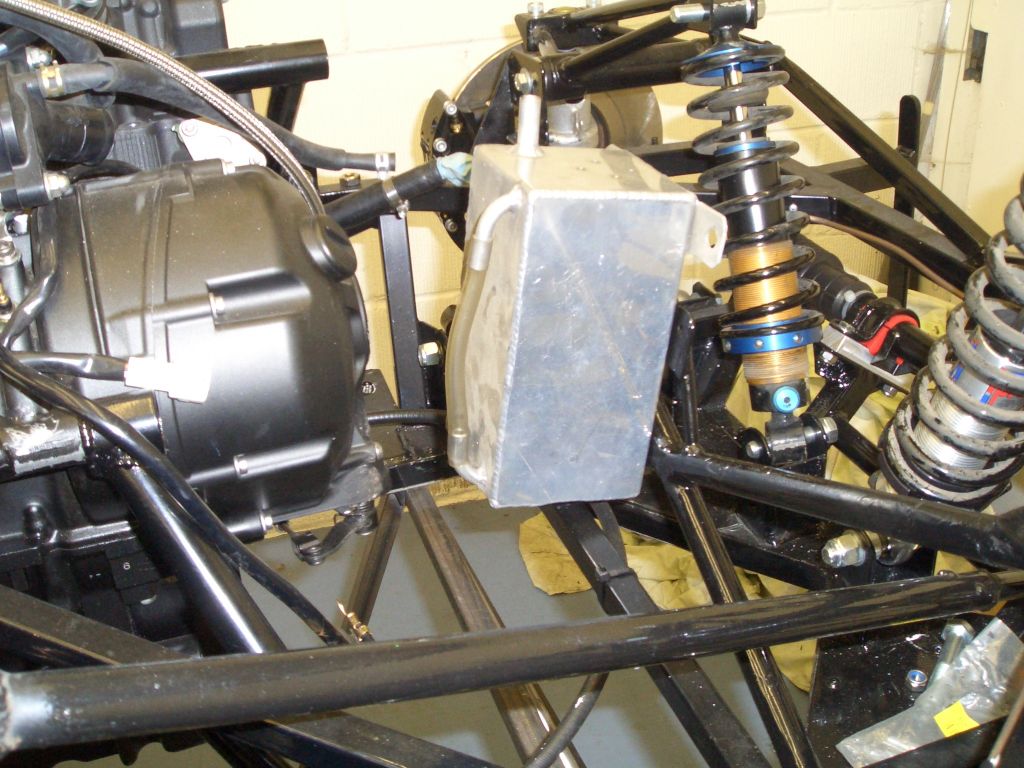
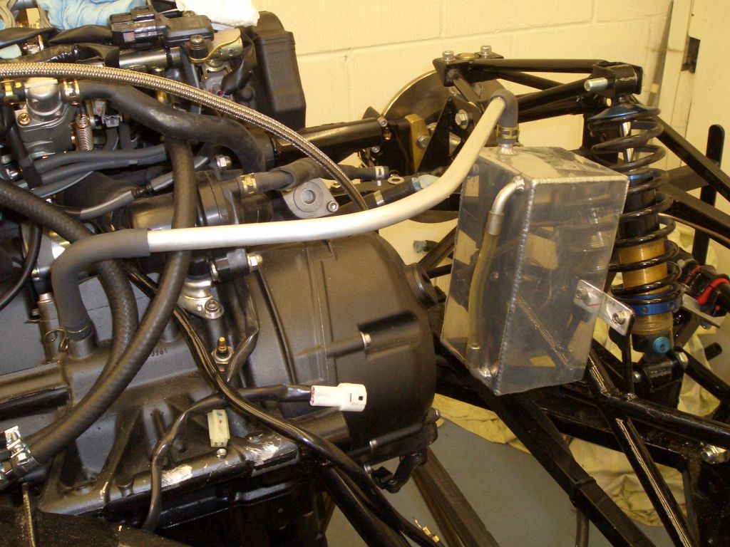
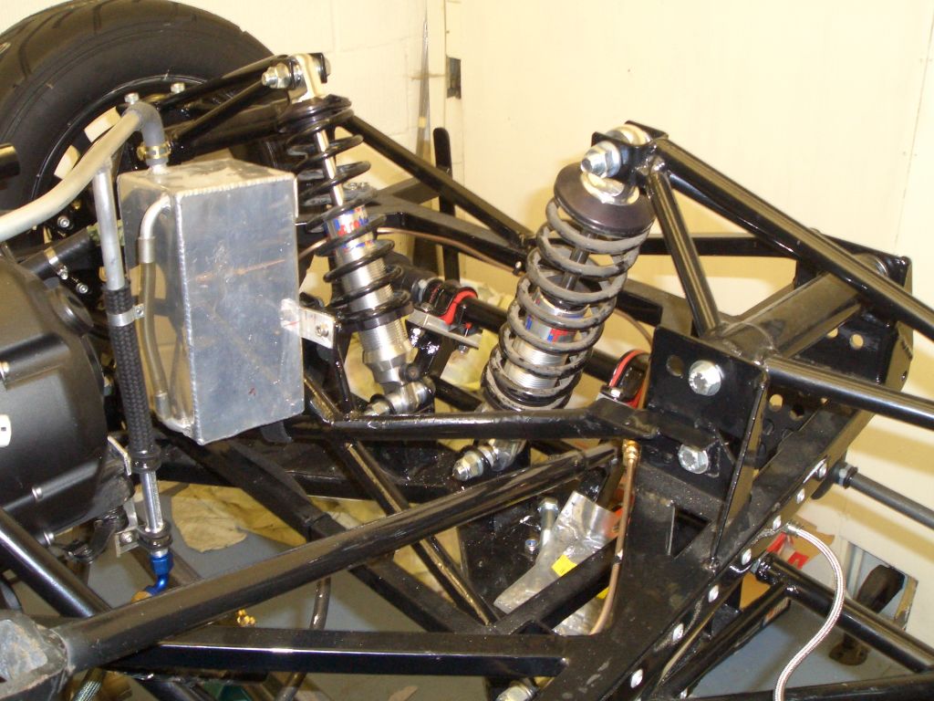
However, one of the relatively few components from the Furybird to make it onto the 'Racer is this suspension cross-brace. The Fury chassis isn't particularly rigid torsionally, largely because the top chassis members along the sides of the chassis are relatively low to allow for doors on the classic Fury bodyshell. This means that the triangles formed within the side panels are relatively slender and, hence, not all that stiff.

I've no idea whether or not this cross-brace actually makes any difference - in theory it should, and it weights precious little since it's made of 18g 3/4" tubing. Strangely, although it fitted the Furybird exactly, one of the mounting eyes needed changing quite a lot for it to fit the suspension (supposedly in exactly the same relative dimensions) of the FuryRacer. I can't be bothered to rant on this point though, it's just too predictable to be worth the effort...

Catch tank

The rules say, quite sensibly, that you have to have a catch tank. The cross-brace pictured above carried out quite a lot of duties in the Furybird - as well as providing whatever assistance it does to the torsional rigidity of the chassis, it also kept the dry sump tank in place, held the top of the oil cooler still and provided a mounting point for the catch tank. Well, there's no dry sump tank on the FuryRacer as it's got a baffled wet sump, the oil cooler is (for now) the factory oil/water heat exchanger, but the cross-brace still provides a handy mounting point for the catch tank.

This is the catch tank that was fitted in the Furybird. However, a push fitting would be better for the 'Racer (the breater's from the engine rather than a dry sump tank) and it doesn't fit anyway as the transverse chassis rail intended to brace the turrets welded in to raise the lower suspension points on the lowered chassis gets in the way.
 

  Fortunately my stash of used aluminium catch tanks also included this one which had a much more suitable hose fitting with a 12mm ali push-on stub which was exactly the right size.

The mounting points were still in the wrong place, but...

...that's why I have a TIG welder. You can see the hacked-off stumps of the old mounting tabs at the top of the tank.  

  Then it was just a question of connecting up the breather on the engine to the catch tank with some hose and bent ali tube. Although in fact, the ali pipe will have to come off shortly so that a T-piece section can be welded on top as this will go on top of the...

Secondary sight glass

It seems that most bike engines don't have dipsticks - they have sight glasses instead (not all, the Blackbird and CBR1000F have dipsticks). This is fine, but the '06 R1 needs to be overfilled by at least a litre over the top of the level of the standard sight glass, which makes it pretty useless - by the time the oil level's dipped below the top of the standard sight glass, your engine's wimpering for mercy and about to put itself out of its misery for good...

So the obvious answer was another sight glass, which would have to be external unless I fancied machining the crankcase to fit another sight glass into that. Actually, it wasn't at all obvious to me, but it was to Steve, and I've nicked the idea off him.

This was my first attempt at the sight glass - graduated Pyrex pipette in the middle, 3mm wall thickness Acrylic tube to protect it, ali bungs holding everything together with a bit of JB weld.
 

It was pretty tough insofar as impacts were concerned, but I broke it 'testing' its strength by bending it - the acrylic tube, despite having 3mm thick walls, was still reasonable flexible, but the Pyrex tube wasn't at all so it snapped. You can see where it's broken in the larger photo. Time for plan B. Plan B occurred to me after I realised that the Pyrex tube needed to be more rigidly supported than it was in the broken part but also that it didn't need to be transparent at all angles.

  This machined ali tube has a 7mm hole up the middle to take the Pyrex tube. At the near end is a JIC-6 fitting I machined (9/16" OD, 18TPI, 37degree taper), it's got a 13mm push fitting on the other end, and the wider sections are 16mm where it's going to be held in place with some 16mm P clips.

The central section is for the sight glass, and just needs a 6mm slot machined in it so that you can see the sight glass which will be inside this ali fitting.

The remote sight glass also needed a fitting on the sump. The 750 Motor Club rules for RGB require that all oil lines have swaged or threaded fittings - push on fittings aren't allowed due to the 'high oil pressures generated by bike engines'. Well, this line isn't going to be under any pressure, assuming the engine breather's getting rid of any blow-by into the crankcase, but I didn't really fancy arguing the toss with a scrutineer about this.

So what I needed was a JIC threaded fitting on the sump. I thought about buying one and welding it on, but I was concerned that welding it would warp the sump, even with TIG. So instead I drilled a hole in the sump (not easy, as the sump wasn't the easiest thing to hold in place)...
 

  ... and made a threaded fitting for it with a JIC -6 male fitting on one end, a 3/8" UNF thread on the other, and a machined ring on the underside of the flange to take a sealing O-ring. And then broke it trying to tighten it up too much. Ah well, only took an hour to make, so the second one won't take as long...

Happily, I managed to fit the second one without breaking it in two. You can just about see the O-ring squashed into the groove machined in the back of the flange on the machined fitting. I'm pretty sure it's not going to leak with that in there.  

  And a picture of the other end on the inside of the sump. I checked before drilling the hole in the sump that the part of the adaptor protruding into the sump wouldn't clash with anything on the engine which drops below the bottom of the crankcase, and it doesn't.

I'd already identified two threaded holes on the engine to mount the sight glass onto. The bracket's a simple bit of bent ali, although it took two goes before getting it right... You can see the slot I cut in the sight glass housing and the Pyrex tube inside (again, held in place with JB Weld adhesive), and the sight glass is mounted using rubber-lined P-clips.

The hose is an Icore Pro-Gold fitting available from Think Auto and Rally Design. The braiding is Kevlar/Nomex and it's pretty light.
 

  The last job on the remote sight glass was welding the T-piece onto the breather pipe from the engine to the catch tank, to allow the sight glass to breathe at the top. The two are connected with a bit of 12mm fuel hose I had left over from the fuel line connections at the back of the car.

Rear dampers

With the new wheels for the FuryRacer on their way I decided to fit the rear dampers which I hadn't got round to before. Which should, of course, be a five minute job. Except that the damper mounts on the trailing arms (that the bottom of the dampers attach to) were to shallow - the mounting hole was too close to the trailing arm itself to allow the damper eyelet to fit into place. The eyelets on the ProTech dampers are quite a bit larger than those on the Spax or AVO dampers fitted as standard on Furies, or the Nitron NTX, as they're all steel-bodied whereas the ProTechs are ali.

I solved the problem by slotting the damper mounting holes, welding new lifter plates with a new hole in behind them, and turning down the spacers which go between the damper mounts and the spherical bearing in the damper eyelet. Only 3 hours' work, all told...
 

  There's not much clearance around the top of the dampers between them and the aluminium panelling....
... or for that matter anywhere else. There is *just* enough, so I don't think any further mods will be required, however. Obviously, there would be more clearance if I'd gone for 1.9" diameter dampers rather than these 2.5" units, but all my springs are 2.5" so it seemed sensible to stick with the same size throughout.

Anyway, if you're working dampers hard (like in a race) the extra volume will help ensure that the damper doesn't get too hot, which can of course affect its damping qualities even with ProTech race-spec oil.
 
Front dampers

  I also got round to fitting the last of the new dampers at the front. Which means the only bit of suspension not fitted is the ARB at the front, which I'm still pondering. I know that in the end I'll just end up copying what Tim's done, but I'm at least trying to make an effort to think of something different in the meantime...

Wheels

Another bit where basically all I do is hand over money and get shiney new parts. In this case, 4 13x6" Compomotive CXRs in black, shod with 185/60/13 Yokohama AO48Rs at the front and 205/60/13s at the back.

One of the good things about Compomotive wheels is that you can order them in pretty much any offset you like (within reason). I've carefully measured
Tim's Fury to see how wide the bodywork is, and then calculated the offset so that the wheels and tyres should fill the wheelarches nicely. I probably ought to get some spares, or at least some scabby RS alloys to put worn tyres on for testing.

Hopefully I'll be able to use this set of rubber before it goes off due to lapse of time and lack of use...
 
Bump steer - LHS

  I'd already checked the bump steer on the RHS of the car when I was making the shims for the DIY steering rack mounts. However, I naively assumed that because I reckoned my fabricating was sufficiently accurate that the rack would be level and straight then if there wasn't any bump steer on the RHS then there wouldn't be any on the LHS.

Then I started wondering whether I ought to check it, so pinched an idea from Gordon Griffin, RGB class A maestro, and checked the bump steer using a laser line generator (one of three I bought ages ago for a project I havne't got round to starting). And either by total coincidence or because actually my fabricating skills aren't that bad after all, there wasn't any bump steer.

In the photo you can *just* see the red line on the garage door, and the yellow thing stuck magnetically to the brake disc is the laser line generator.

Fuel lines

Other than fitting the fuel tank (ordered but not yet delivered) and connecting it up the only fuel plumbing job left to do was to connect the 8mm outlet from the pre-filter to the 12mm inlet on the fuel pump. Bit of 12mm fuel pipe, a 12mm-8mm steel adaptor I made on the lathe, some 8mm fuel hose and some fuel clips and it's done.