This in turn meant it was necessary to chop down the track rods as otherwise they'd foul the rosejoints - as you can see they overlap, which they wouldn't be able to do once the TRE adaptors were fitted.
| Yes, another rather late update. But to be honest, I haven't had time to do much work on the FuryRacer during May - I had to get the Striker ready for the se7ens list Mischief on the Moors tour, get the Ginetta ready for the same tour, do the tour, and it was my brother's wedding. So, all in all, not much FuryRacer fettling time. Still, I have got a few things done... |
| |
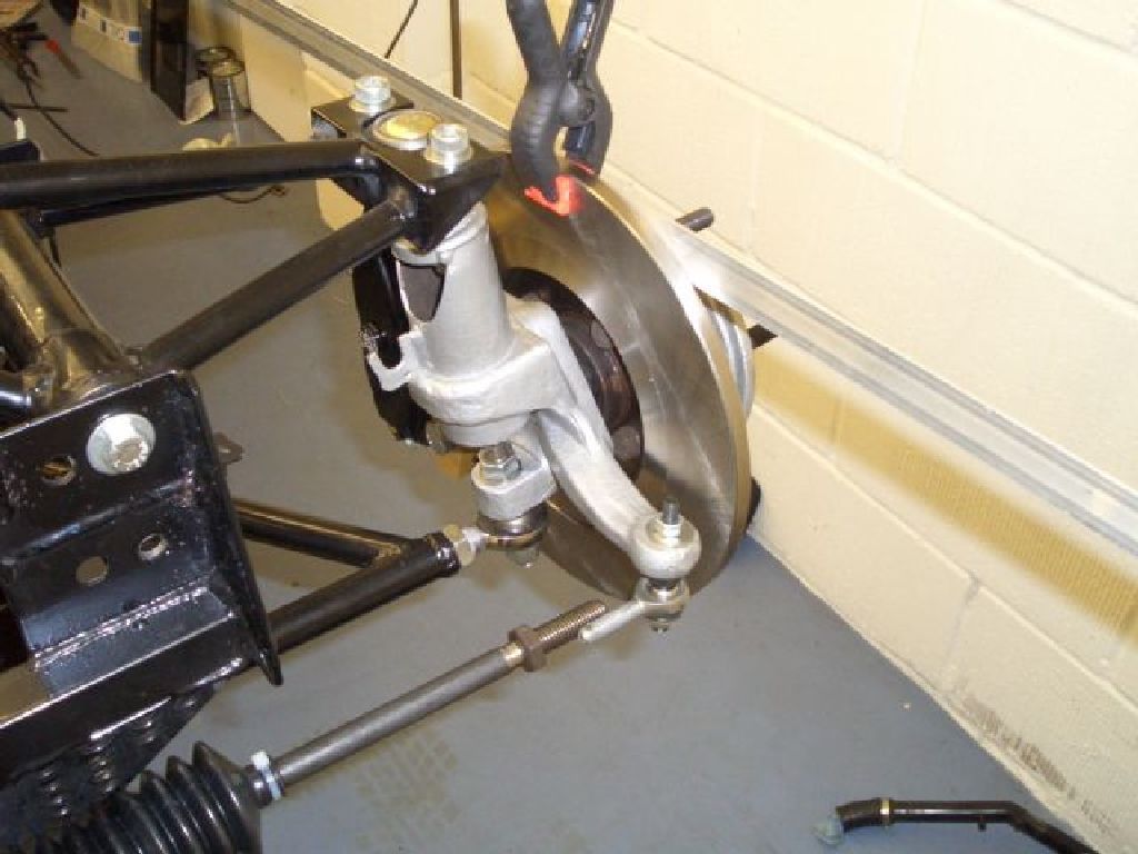
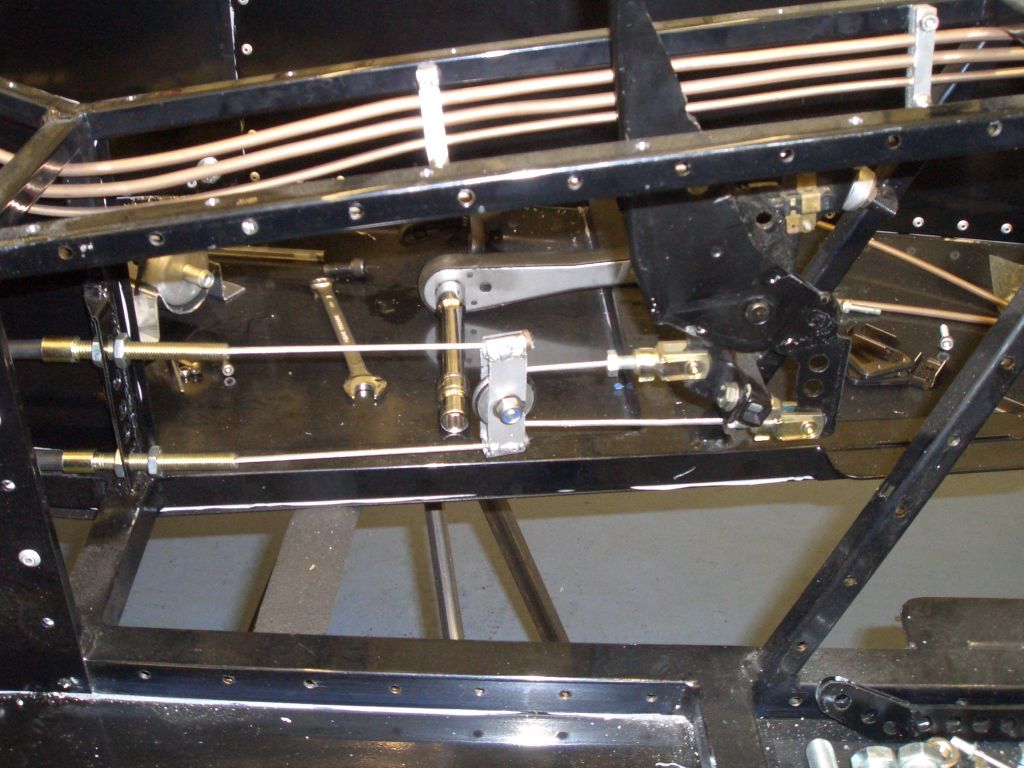
Given that I'd deliberately made the steering rack mounts shorter than
they needed to be, it was necessary to shim them up into place to get ride of the bumpsteer which would result
from the steering rack being too low. In order to check the bumpsteer, and therefore work out how much the rack
needed to be shimmed by, it was necessary to fit the TRE adaptors I'd made up. This in turn meant it was necessary to chop down the track rods as otherwise they'd foul the rosejoints - as you can see they overlap, which they wouldn't be able to do once the TRE adaptors were fitted. |
 |
This meant I could fit the TRE adaptors on the uprights and to the track
rods. Then, with the springs off the damper bodies, I could raise the suspension up and down, and by comparing the angle (if any) between a length of ali clamped to the brake disc, and a lenth of steel on the ground, see if the toe for that wheel was changing during the suspension travel. As anticipated, with the unshimmed rack there was a lot of bump steer. So I made up some 19mm ali spacers, and machined them down little by little until I'd got rid of the bump steer. |
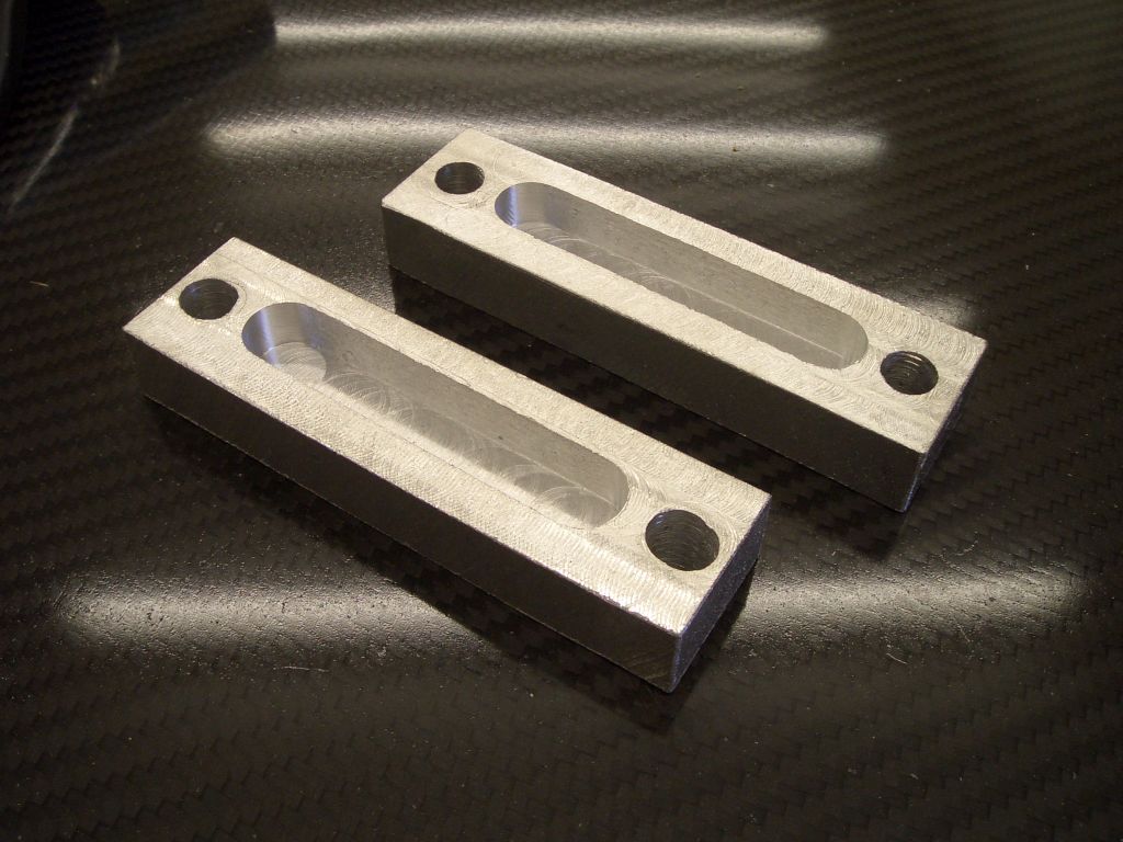
| This was, of course, an amazingly boring and time-consuming process
but eventually I'd got rid of the bump-steer, or at least got rid of it insofar as my rather crude testing set-up
could measure it. I may end up making a rather more sophisticated bump-steer gauge later, but this will do for
now. And here are the finished spacers. They ended up being about 12mm thick, and as you can see I machined some slots into the backs just to save a bit of weight. Because of the need for the spacers, the whole steering set-up is marginally heaver, which is annoying, but sadly just another consequence of the chassis being made so poorly. |
 |
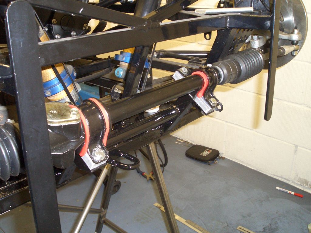 |
Until I make up a more accurate bump steer gauge and feel the need to reshim everything, the steering rack is now officially done. And just to wrap things up, here it is in all its glory, complete with shims. |
| Earlier in the build, I'd fitted the handbrake lever and made a connecting
linkage and compensator bar to connect it to the handbrake cables. With the handbrake cables fitted, I made up
some home-made cable ferrules and fitted the cables into them, soldering the ends into place. When it was all fitted together, it did work after a fashion. But not terribly well. The problem was simply a lack of mechanical advantage. The handbrake actuating levers on the Powerlite HB calipers are very short, so there's little leverage to help you there. Also, the modifications to the Sierra handbrake lever, to make it work in a vertical position rather than horizontally, inevitably involve extending the lever at the end where the handbrake cable connects to it. This reduces the mechanical advantage provided by the lever as a whole, since it moves the point where the force exerted through the lever is applied further away from the pivot. So I was going to need to improve the mechanical advantage the system as a whole provided. |
 |
 |
There are only a limited number of solutions to this problem - make
the levers on the calipers longer (not feasible), make the handbrake lever longer (not attractive as an option)
or introduce a new element which will provide further mechanical advantage. I then remembered one of the many doomed variations on the handbrake system we originally built for Zena's Ginetta, which inadvertently caused a bolt, around which the handbrake cable ran, to act as a pulley and double the mechanical advantage provided by the system. In the case of Zena's Ginetta, this meant ending up with too much mechanical advantage, but in this case it seemed like a pretty good solution. The only problem was drilling a hole in the handbrake lever for the stationary end of the secondary handbrake cable to go. The whole thing's case hardened and I ended up almost having to melt my way through with the TIG torch before the metal was soft enough for a drill bit to anything whatsoever. |
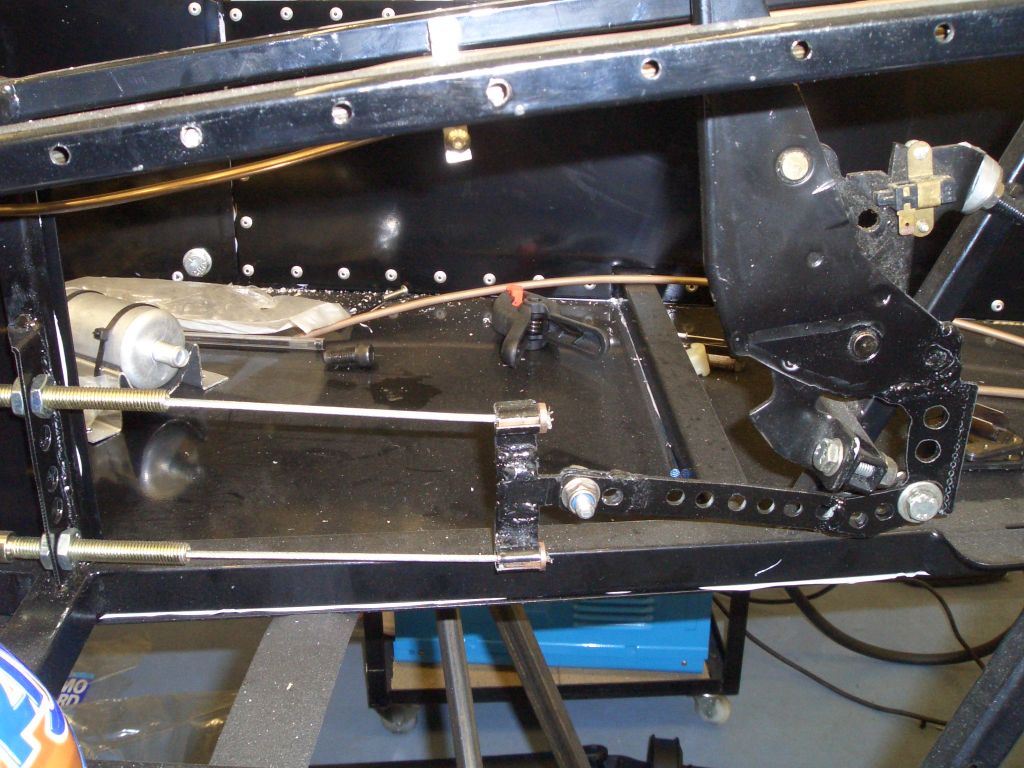
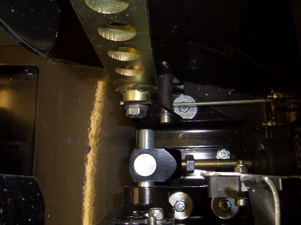
| The version above was pretty good, except because the pivot for the
pulley (an acetal pulley I got from the local boat-chandlers for 50p) is slightly behind the end of the cable stops
on the compensator, when you pull the cable the compensator gets pulled sideways as the pulley tries to overtake
the cable stops. So I made up a third compensator, to the right, which gets everything lined up rather better. The home-made cable stops have held this for 5 days now, with everything as tight as I can pull it using a 1 metre long bit of steel to move the handbrake lever backwards. So far it's all held. In fact, the only problem at the moment is I can't work out how to release it because the handbrake's on so hard... |
 |
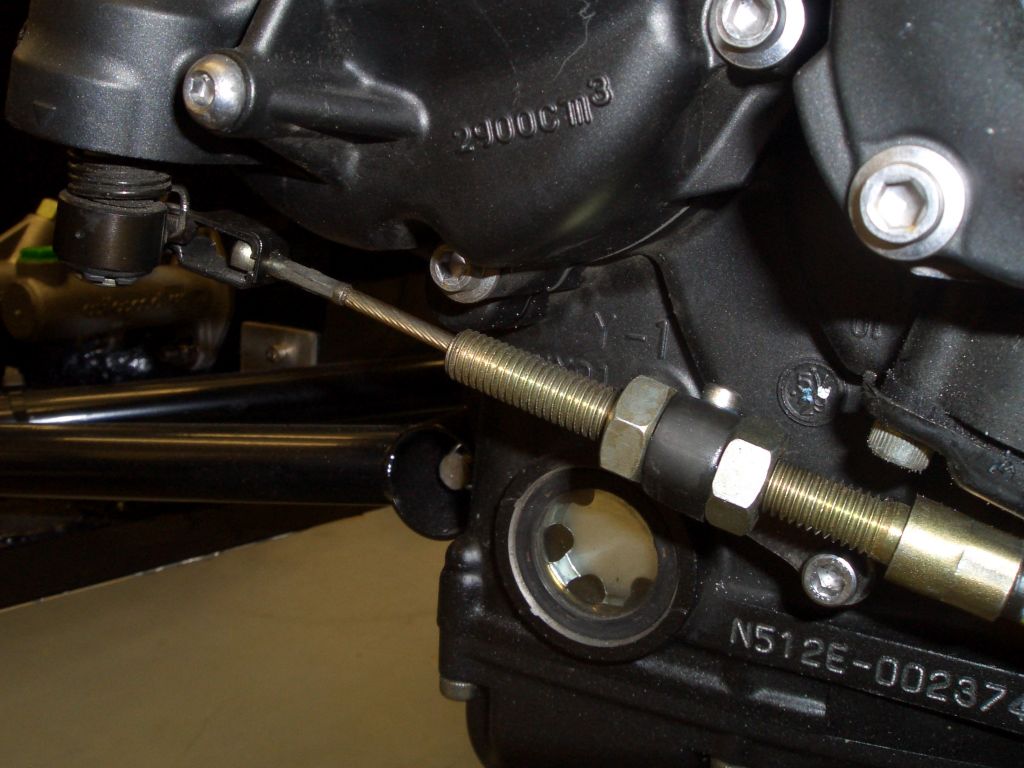 |
The clutch on the 2006 R1 engine (in common, I think, with all R1 engines)
is cable operated. This makes it a lot easier to rig up a working system when compared to the hydraulic clutches
on the Blackbird, CBR1000 and PanEuropean engines I've worked with before - no issues of clutch slave cylinders
wanting to get friendly with propshaft yokes, for instance. With only a vague idea of what I needed, I bought a Ford clutch cable off eBay - the Quentin Hazel part number is QCC1000. This was almost perfect in fact. The cable nipple at the engine end needed filing down a bit, and the cable stop attached to the engine needed opening up a bit to take the treaded adjustment section, but other than that it all fitted together reasonably easily. |
| At the other end I had to make up an extension piece 40mm long to, effectively, extend the outer cable by 40mm to ensure that the cable stop at the engine end fell within the range of the threaded adjustment bit of the outer cable. An M6 bolt through the holes in the clutch pedal and the hole on the clutch end of the cable, and everything was in place. | 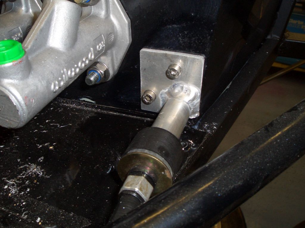 |
 |
The only other job required on the clutch was to add a pedal stop to
prevent the clutch pedal from falling forwards over centre and producing too much slack in the cable. Because I
had to add the extensions to take the clutch pedal myself, due to the pedal box having been cut down before I got
it, there wasn't any form of pedal stop. There is now, in the form of an M6 bolt and some 6mm ID fuel tubing. I can't remember which build diary it was that gave me the idea of using the fuel tubing to provide a soft pedal stop, but whoever it was, cheers! |
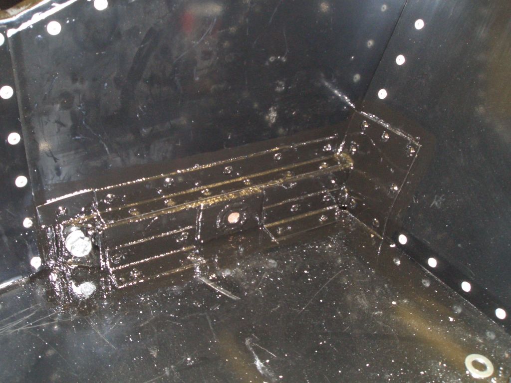
| In order to rectify the wonky chassis I'd had to cut away parts of the
internal panelling around the misplaced chassis member in order to cut it away and weld in a new one. In order
to keep all the remaining bits together, I made and fitted patch panels from ali angle and ali sheet to fill in
the holes and connect the floorpan and side panel to the new chassis rail. The only section of panelling which I removed and didn't replace is a small triangular section in the floorpan - it's only tiny and the resulting hole can serve as a drain hole... The result is very far from being aesthetically pleasing but thankfully the seat will totally obscure it. |
 |
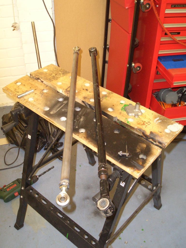 |
Finally for this month, I decided to make a new Panhard rod. Even with
the new and improved chassis member there's still precious little clearance between it and the trailing arm, and
as such I was a bit concerned that the compliance provided by the metalastic bushes at the ends of the old Panhard
rod I'd salvaged from the wreck of the Furybird would provide enough slack for the two to come into unwelcome contact.
In fact, I think it's pretty unlikely that this would ever happen, but better safe than sorry... The new one's on the left and is made using the tried and tested method of turning down some 1/2" UNF threaded bosses from Rally Design and welding them into 7/8" CDS steel tubing. Whereas the old Panhard rod had a threaded adjuster built in at one end, the new rod can be adjusted by winding the rosejoints in and out. I've used lower spec rosejoints for the Panhard rod than I've used on the front of the car - they're only going to be subjected to radial loads and as such the higher spec joints shouldn't be necessary. The new Panhard rod is certainly considerably lighter than the old one. I haven't measured the difference, but it's noticeable when you pick them both up together. For one thing, the tubing walls are a lot thinner, and also the rather chunky threaded adjuster is gone. All that's needed now is to paint and fit the Panhard rod, and adjust it so that the rear axle is (at last) central in the chassis. |