18th April 2007

Engine - sump baffle

  Given my two engine blow-ups with the Furybird, I'm keenly aware that oil surge in high-revving engines is A Bad Thing. And quite often An Expensive Thing. The received wisdom before I started the build was that 2004+ R1 engines don't suffer surge if they're fitted with a baffle plate and overfilled. Subsequent experiences in the RGB series suggest that this may not necessarily be true, but I live in hope. Anyway, a baffle plate was hardly going to make things worse.

So I bought a baffle plate from Jonathan Rarity, and took the sump off the engine to allow me to fit it. It never ceases to amaze me, whenever I whip the sump of one of these Japanese bike engines, how small and perfectly formed everything is, and also what a lot of space there is in there.

Fitting the sump baffle was entirely straightforward, so here's a picture of it in place.

It's noticeable that some of the holes in the baffle plate are very close together, leaving little material between them. I assume that's one reason why the printed instructions that come with the baffle plate suggest inspecting it at least once a season for cracks and other damage.

Having refitted the sump with a new sump gasket, the engine was ready to go in the car.
 

Engine installation

  Given that I've got an engine crane to help me, getting the engine into place was pretty simple. Getting the engine mounts into place and bolted down was of course a complete swine of a job, since the welding process had distorted them slightly. However, by using progressively larger hammers and progressively more profane swearwords, the engine and mounts were persuaded into place.

The only real problem was the rear engine mount. I'd made this using the 2005 engine which doesn't have an alternator cover fitted. Naturally, the engine mount fouled the alternator cover on the 2006 lump. Even when I 'relieved' the engine mount to clear the alternator, another problem arose - I'd made the engine mount before I'd panelled the chassis, and the aluminium plate at the end of the passenger footwell along with the rivets holding it in place meant the engine mount could no longer nestle up lovingly against the chassis rail at the top of the PX footwell, as it was intended to do. I'll have to make another one, but I haven't got round to it yet.  

Rear axle installation - dampers

  I'd already replaced the metalastic bushes on two of the Nitron dampers (during the early stages of the FurybirdII build, as I had originally planned to use them on the Furybird), and they were fitted on the front of the car. That left the two rear dampers to do. This was a question of drilling, machining and sawing to remove the old bushes (the lefthand damper on the picture on the left). Once it was out (without damaging the damper itself) I could press in the high angularity spherical bearing using the vice, a socket and lots of studlock.

Rear axle halfshafts and brake calipers

Getting the rear axle into place single-handed wasn't much fun, but with the asistance of a trolley jack and some ratchet straps I managed it eventually. Next I fitted the halfshafts (with the new bearings fitted by Midway Garage and with new longer wheelstuds that I fitted), and bolted the bearing retaining plate into place. The retaining plates are fitted with longer bolts than normal as these have to hold the caliper mounting brackets in place as well as the retaining plates.  

  These are the caliper mounting brackets which bolt onto the halfshaft using the longer retaining plate bolts. As you can see, they're pretty close to the disc. As it turned out they were rather too close - in order to provide for some clearance between the caliper mount and the disc it was necessary to shim the caliper bracket in towards the centre of the car using a couple of thin stainless washers.

It also proved necessary to add some shims between the caliper and the mounting bracket - without them the handbrake lever on the caliper hit the disc and the caliper wouldn't sit squarely on the mounting bracket. Again, two thin washers were necessary, and I also relieved the bottom of the handbrake lever (with an angle grinder) so that 2, rather than 3, washers were all that was necessary.

This reduced the extent to which the pads extended beyond the outside of the brake disc and hopefully means I won't have any clearance issues - it's a pretty tight fit between the handbrake levers on the caliper and the rim of a 13" wheel, so every little helps.
 

  With the shims added, there's still not a whole lot of clearance, but there is a little, which is all that's necessary.

And there they are - very nice.  

Front brake calipers

  The front brake calipers went on fairly easily, the only difficulty being that the kit comes with 7/16" UNF bolts to attach the calipers mounts to the upright. That's fine for Escort MkI uprights, but the MkII uprights have M12 holes instead. This meant I had to go and get some 30mm M12 bolts, but other than that (and a little filing and shimming) the front calipers didn't put up too much of a fight.

Pedal box and master cylinders

I was hoping to use the 2 3/4" master cylinders off the Furybird1 on the racer, but the rear MC was too large - the pistons on the Wilwood handbrake calipers are quite small, certainly when compared to the Sierra calipers, so in order to maintain the same brake bias as I had before it was necessary to use a .625" MC for the rear brakes.

Once I'd got this I fitted the pedal box, along with one of the old .75" MCs. However, it turned out that the old .75" MC had seized - presumably the old brake fluid in it had attracted water, despite my best efforts to seal it, which had caused it to rust internally. Anyway, given the rather modest cost of Wilwood MCs from Rally Design, it was hardly worth rebuilding it, so I just bought a new one. So both of the old MCs went in the bin...
 

  Once the brake pedal was in place I knocked up some little ali brackets to hang a microswitch off and to actuate it. When the brake pedal goes forwards the microswitch is released and will switch the brake lights on. There's over 2 inches travel at the pedal before things start hitting each other in a bad way - and if I've got that much travel in the brake pedal, I've got far more serious issues than a bent microswitch bracket...

28th April 2007

Even more chassis problems

Earlier in the build, I'd discovered a problem with the way the chassis had been welded - the trailing arms wouldn't fit in the brackets they were intended to go into, with the result I had to chop them off, fabricate some new ones, and weld them into place.

I'd thought that this was the only problem with the chassis - not so. Having fitted the rear axle, I fitted the Panhard rod which locates the axle laterally. The Panhard rod is adjustable, so can be used to ensure that the rear axle is central relative to the chassis. I initially set the Panhard rod up so that the gaps between the trailing arms and the 10mm steel plates on the outside of the chassis were equal on both sides. In the process, I noticed that it was necessary to adjust the Panhard rod to a much longer length than had been necessary on the Furybird.

Once it was in place, I checked the location of the rear axle by reference to other parts of the chassis, and immediately something seemed wrong. For instance, the leading arms at the top of the chassis were at different angle.

  The picture on the left shows the right hand side leading arm. At the top of the photo you can see the tube in which the metalastic mounting bush at the front of the leading arm is located, along with the tubular body of the leading arm running underneath the chassis rail. The leading arm is clearly on the outside of the chassis.

Not so on the other side. It's not a great picture, but you can just about see the same mounting tube on the inside of the chassis, with a nut just next to it. There's certainly no part of the leading arm outside the edge of the chassis.  

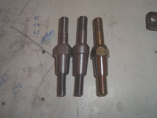
At first I assumed it was my modified trailing arms that were the problem. But they weren't - they were well within the tolerances that the rest of the chassis appears to have been built 
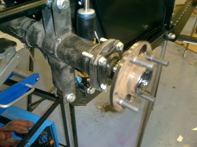
to (i.e. +/-3mm...). Then I thought the axle might have been bent in the crash. It might have been, but not enough to explain the offset. Then I wondered if the suspension mounts welded onto the axle might be bent. They were, 
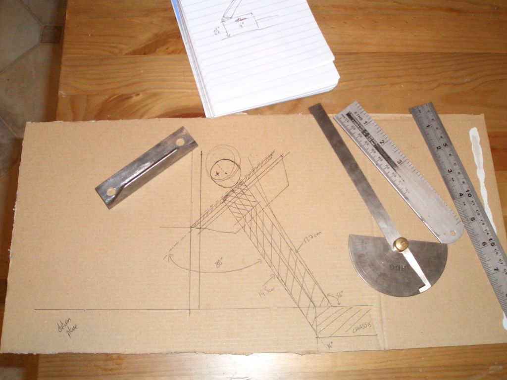
but again, not enough to result in the axle being an inch out of line. Eventually, after a lot of measuring and pondering, the root cause of the problem became pretty clear.

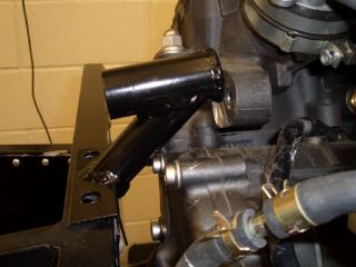
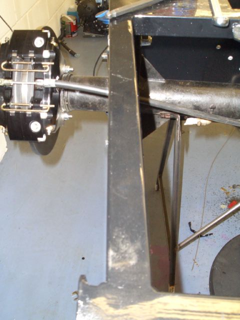
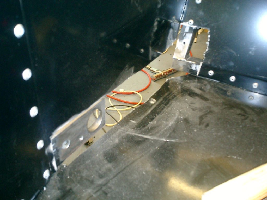
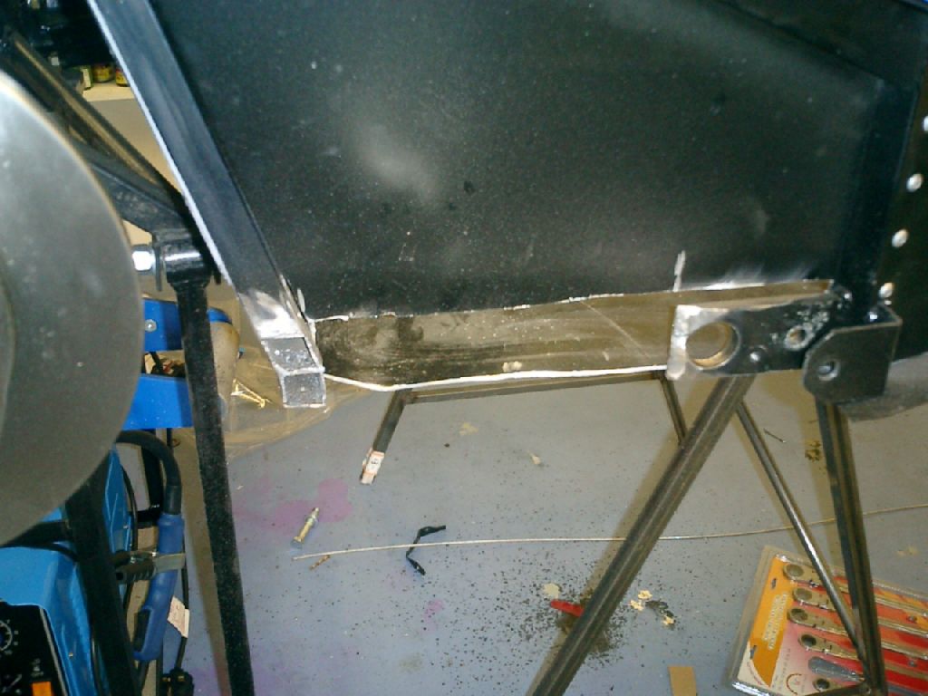
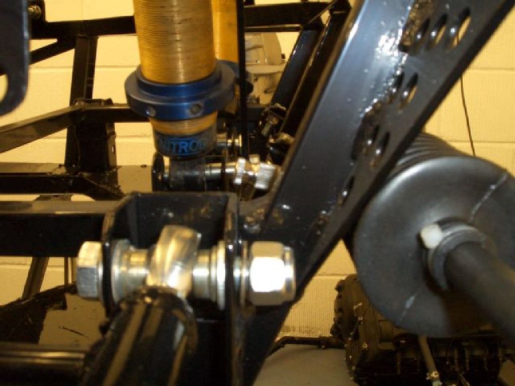
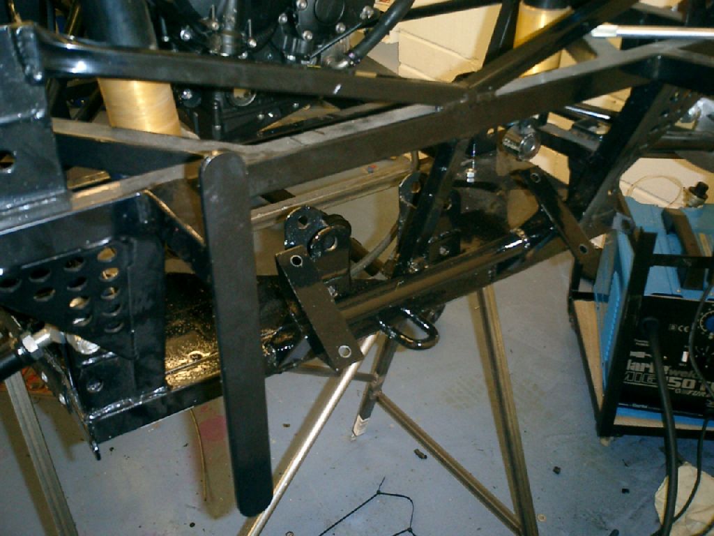
The problem is that the whole of the bottom rear part of the passenger/driver compartment has been welded on at an angle. Basically, a substantial part of the chassis is wonky. Because this part of the chassis runs very close to the trailing arms, the angle of this part of the chassis (and the 10mm steel plate sections in particular) define where the rear axle sits relative to the rest of the car. And because the chassis is wonky, the rear axle isn't central.

This is, of course, once again A Bad Thing. The rear wheels are supposed to be behind the front wheels, not wandering off to one side.

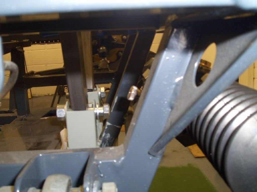
I ended up taking quite a few pictures and measurements to satisfy myself that the chassis was indeed lopsided. Rather than bore everyone with all the minutiae here, true lovers of bent chassis pictures can take a look
here.

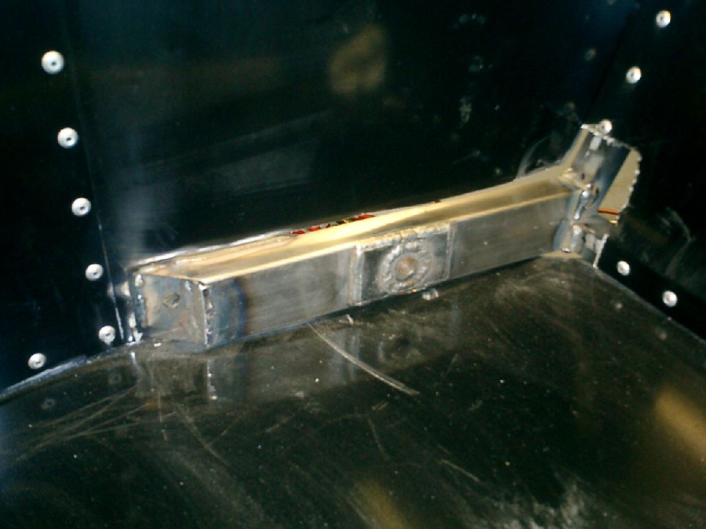
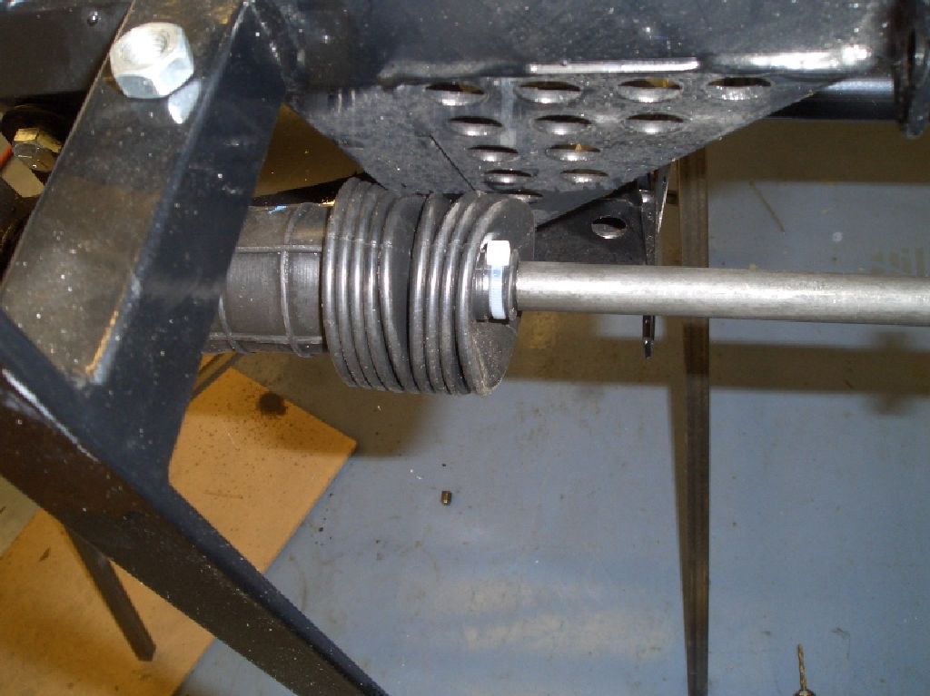
In order to allow the rear axle to run centrally relative to the chassis, it was inevitable that the 10mm plate on the driver's side had to go. The trouble is that it's a fairly integral part of the structure, not to mention that the lap and crotch straps mounts for the driver's safety harness are welded to it. So it had to go, but it also had to be replaced.

  Happily, with my custom carbon seat there's a fair bit of room at the sides and so it wouldn't be too difficult to add a new chassis rail further inboard. The first step was to cut away the aluminium panels (yup, those ali panels I'd spent so long getting powder-coated and so long fitting) around the places where I'd need to cut and/or weld. I decided that it would be easier to do this on a piece-meal basis rather than remove the whole panel - due to the overlapping nature of the panels this would have meant removing most of the panels on this side of the chassis.

Then I chopped out the 10mm plate section. I thought about bracing the chassis temporarily to make sure nothing moved when I did so, but frankly the chassis is built to such lax tolerances I couldn't see the point.

The net result was the large hole in the chassis shown in the picture on the left.

And for good measure a picture of the same thing from the outside of the chassis.  

  I then welded a length of 2" x 1" tube between the stump of 10mm plate left on the chassis and the rear upright chassis member. The hole in the middle is a 7/16" threaded boss from Rally Design with a 3mm steel spreader plate welded around it. The heat of the welding actually made the 2" x 1" tube bend slightly, but in fact this meant it fitted rather better than it would have done if it was straight...

Steering - track rod adaptors

With the rear of the chassis now bodged into something approaching symmetry, I thought I'd try and finish off the steering. Having already made the adaptor pins to go in the uprights the next thing to do was made the track rod adaptors that would link the track rods (M14 x 2.0 coarse thread) with the male rod ends (3/8" UNF).

And here they are. Very nice, though I say it myself. Actually, the one on the left is the Raceleda one, and the one on the right is the one I made. The carbon sheet they're resting on is a bit of pre-preg I made a while back - I'm rather pleased with that too... ;)
 
Steering rack mounts - they're wonky too...

  The track rod adaptors fitted perfectly first time. Then I tried fitting the intermediate steering column - this links the Escort Mk2 steering rack with the modified Sierra upper column. After I'd eventually wrestled it into position, it was immediately apparent that something was wrong.

For one thing, I'm fairly sure that the steering column's not supposed to go
through the footwell. For one thing, it'd mean moving the brake pedal somewhere rather inconvenient. Like on the dashboard...

On even a cursory comparison of the steering rack positions on the FuryRacer and the Furybird2 it was clear that the FuryRacer steering rack mounts were at the wrong angle. Here's an amazingly pony photo (click on the photo and you'll get a larger if still rather blurry version) of the steering rack pinion on the FuryRacer...  

  ...and here's the one on the Furybird2. Fairly obviously, they're at different angles.

I think the reason is that the pinion shaft on the Escort Mk2 steering rack isn't parallel with the flat plane at the base of the rack which rests on the steering rack mounts. And I suspect that whoever welded the steering rack mounts on the FuryRacer chassis forgot (or didn't know) this.

Whatever the reasons, it appeared that Mr. Incompetent Mig Monkey had also waved his magic blue welding crayon of ineptitude over the steering rack mounts, after he'd finished screwing up the rest of the chassis.

Now I'd been thinking about replacing the rubber disc at the bottom of the intermediate shaft with a Group4 Escort UJ like I've used on my home-brewed steering column for the Furybird2. Somehow, a big lump of rubber doesn't seem the most appropriate material to have in a racecar's steering system. And this would easily cope with the misalignment in the steering rack.

But Mr. Incompetent Mig Monkey hadn't limited himself to buggering up only one part of the steering rack mounts. Oh no, he'd done a pretty comprehensive job of getting it completely wrong. He'd also put the steering rack mounts too close to the chassis so that the gaiters rubbed, fairly comprehensively, on a chassis tube. In fact, when you turned the steering, you could feel the ribs in the gaiter shuffling their way past the chassis.

I'm fairly sure Mr. SVA man won't approve, and I certainly don't - steering rack gaiters, in my book, are there to stop muck getting in the steering rack - not to ensure that any steering feel you might otherwise have is completely lost...
 

  ...and just in case you thought Mr. Monkey hadn't ballsed it up enough, it turns out the steering rack wasn't even straight. I've put red tape on it to provide a bit of contrast, and you can see that it's not parallel with the top chassis rail.

Of course, it may well be that it's the steering rack that's straight and the top chassis rail that's wonky. Who knows? By this stage I'd already decided that the steering rack mounts were another thing I was going to have to do myself if I wanted it done properly.

Steering rack mounts - removal and replacement

So, some pre-emptive apologies for the noise to the neighbours, 2 grinding discs, an hour of griding and one small fire later, and the problem of the incorrectly situated steering rack mounts is solved. Now the only problem to solve is the total lack of steering rack mounts.  
  Welding the steering rack mounts into place on a chassis jig is, I imagine, fairly easy. Presumably you'd even have templates for the steel making up the mounts. Although the evidence suggests that this probably wasn't the way this chassis was made...

In order to try and do a slightly better job, I measured the mounts on the Furybird2 chassis, and drew them on a piece of card. Yup, this isn't 'back-of-a-fag-packet' engineering. It's back-of-a-Dremel-drill-box engineering. I deliberately made the rack mounts shorter than I anticipated they needed to be - I can always add shims to get the rack in the correct position, while I've run out of anti-shims which would be necessary to get it lower down.

Lots of measuring, cutting, drilling, filing and welding later, not to mention 2 coats of etch primer and 2 coats of black POR15, and the chassis has regained its steering rack mounts. I've checked, and these ones are in the correct place, although as anticipated they need some shims to move the rack up to dial out some bump steer. However, the intermediate steering shaft points above the pedal box, the gaiters don't hit the chassis, and it's (marginally) less wonky than it was before. Not perfect, perhaps, but a distinct improvement.  

I'm currently hoping that this will be the last chassis rectification work that's necessary and that I can now get on and build the damn thing. Mind you, I thought that when I found the first evidence of Mr. Monkey's workmanship. We shall see...