7th March 2007

Pipework

  This is the first build I've done with an injection engine. A relatively minor point, but it does add a little extra complexity such as the need for a return line from the fuel rail to the tank. That means that as well as the loom it's necessary to squeeze 2 fuel lines and a brake line down the transmission tunnel.

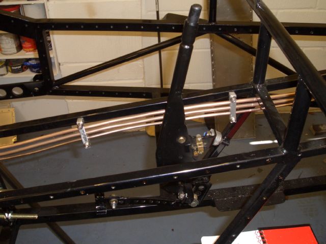
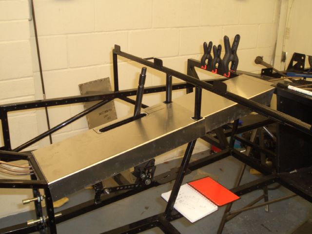
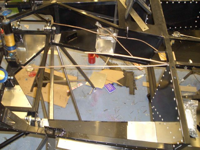
Now, I don't really like running stuff like that along the bottom of the transmission tunnel. Don't know why really, I just prefer having it at the top. But that makes it all rather a squeeze, so I decided to put the fuel rails and the brake line along one side, all held in place with some blingy aluminium split clamps. And there they are. Lovely.

Pointless, really, but lovely. Of course I should really have put them all down the other side to avoid them having to pass so close to the handbrake, but at the time I installed them the handbrake wasn't in place and I wasn't awake enough to spot the potential problem...

Handbrake lever

The handbrake lever on the Fury is mounted on one of the chassis tubes at the side of the transmission tunnel on the passenger's side. In its normal position it's too far forward for me to reach if I'm sat right back in the car, so I made up some angled ali spacers to tilt it backwards a bit.

Also, due to the way it's mounted, the handbrake needs to be modified by moving the mounting point for the handbrake lever downwards - it's designed to be mounted horizontally rather than vertically, so the lever itself gets in the way of the handbrake cable if you use the standard mounting point. The answer was to weld on an extension going downwards below the lower mounting point.
 

  For the rear brakes on the racer I've decided to fit Powerlite handbrake calipers. The rear axle was bracketed to use Sierra calipers, I had some fully functioning Sierra calipers and some discs to go with them. But the Powerlite one's a much pimpier, so I bought some. The handbrake cables come as two separate cables rather than a looped cable like the Sierra one. Nonetheless, I could have joined them together and used a compensator quadrant from a Sierra cable.

However, I decided (on what grounds I'm still not quite sure) that it would be easier to have ferrules put on the end of the cables rather than getting them joined together. So to act as a handbrake compensator, so that the force applied by the handbrake lever to each of the calipers is roughly equal, I've made this rather elaborate device. In operation it won't be resting on the lower chassis rail, of course.


I also needed to add somewhere for the adjustable cable stops on the lever end of the handbrake cables to bolt into, so welded in this strip of steel. Of course, I first made sure that there was going to be enough room left for the propshaft, and there is. Probably.  

Lower front wishbones

  Wishbones are not, after my experience with the lower front wishbones on the Furybird2, something I'd get from the factory, frankly. The ones for the Furybird2 were inordinately expensive, difficult to get hold of, and too short. OK, so they were custom made because I wanted to use a 5/8" shank rosejoint on the bottom of the upright, but I wasn't going down that route again.


And since I had to make up two wishbones for the Furybird2 anyway, I thought I may as well make up another two for the racer. On the left is the jig - not exactly sophisticated - just MDF with steel angle, the steel angle having holes in it where the threaded parts of the wishbones are going to go.

This shows the jig with the steel tubing in place ready to be welded. The threaded bosses are from Rally Design and I turned them down on my lathe so they were a sliding fit inside the CDS tubing (a mixture of 7/8" 16 gauge and 22mm 1.5 wall thickness tubing). Once again copying Tim entirely, I've added some 1/2" CDS tubing between the two bosses which hold the rosejoints which attach to the chassis.


Once in place, the wishbone can be tack welded and then taken out and welded up fully. I decided in the end to MIG weld the wishbones rather than using the TIG simply because it's faster and less of a faff.
 

  On the left are all the parts for 4 lower front wishbones. Four 5/8" UNF bosses, 8 1/2" UNF bosses, four diagonals, four 1/2" tubes, and the long and short tubes that go at the front and rear of the wishbone respectively.

And this is what they look like when they've all been welded up using my nice new MIG welder (that was the other reason I decided to use MIG not TIG). Now they just need to go off to the powder-coaters (a recurring theme).  

17th March 2007

Track rod end adaptors

  It seems a bit of a pity to have the front suspension running on rosejoints and roller-bearings and then have the steering articulation provided by nasty old Escort balljoints. Apart from anything else, I dislike tapers, especially on racecars where you're going to want to change the set-up quickly.

Raceleda used to do a very nice conversion kit to allow you to run rosejoints instead of wishbones - I bought a set for the Furybird2, and a piccy of it's on the left. Not cheap, but once you added up the cost of all the parts, not too bad.

The bad news is that Raceleda went bust. The good news is that the rights to make this kit were bought by MNR Racing. The second bit of bad news is that they really don't seem very keen on selling them to anyone.

So sod 'em, I'll make my own. Some 19mm BMS bar, an hour of two on the lathe, and there's a couple of the steel adaptor pins. The Raceleda one is of course the one on the right - the two on the left are the ones I made up.

In order to try and stop them from corroding when they're in place, I've blacked them by heating them up with a blow-torch and dipping them in old engine oil. This gives them a nice black finish which is reasonably corrosion resistant. It does, however, involve making vast quantities of smelly white oil smoke, so next time I do it, I won't do it by the open back door to the house...

I still need to make up the ali adaptors which go on the ends of the track rods, but they're relatively straightforward.
 

Transmission top panels

  The set of ali panels I got from Fisher Sportscars included pre-cut panels for the top of the transmission tunnel. However, if you fit them and the panels on the side of the transmission tunnel you end up with an SVA unfriendly sharp edge. This is also the sharp edge I broke four ribs on when I crahsed the Furybird, so I'm keen not to have any on this car.

To kill both birds with one stone, therefore, I've started making transmission tunnel top panels that curve round onto the sides of the transmission tunnel. Although you probably can't see it in the photo, the bottom edge of the panels is folded over upon itself, so it should be entirely SVA friendly. As you can see, two of them are done (although they still need a bit of tidying up) while the third still needs to be bent into shape.

Engine delivery

OK, this isn't really anything I've done other than hand over some money, but to Malc from Yorkshire Engine Supplies. It's a 2006 R1 engine which has done less than 600 miles and comes with all the bits I need (at least, I hope it does given the price I paid for it).  

Rear caliper brackets

The original intention with the FuryRacer was to get a new chassis, engine and bodyshell and make a new car using the old bits left over from the Furybird2 build. Nice and simple, in other words. Needless to say, project creep crept in before the build even started. An example of this is the rear calipers.

The rear axle on the Furybird was bracketed for use with Sierra rear calipers and Escort MkIV solid front brake discs. It wasn't that pimpy, but it worked perfectly well. However, before the Furyracer build started, I was tempted by some Powerlite handbrake calipers so I got some.

A bit later I decided I would use the standard Rally Design handbrake cables designed for use with the Powerlite HB calipers so I bought some of them. Then I discovered that the Powerlite calipers wouldn't work with the Escort 240mm discs as there wasn't enough of a swept area, so I got some of the brake discs which Rally Design use on their Powerlite HB kit for an English rear axle. They fitted no problem, but it turned out that the bracket for the Sierra rear calipers was in the way, so I ended up ordering a pair of the brackets Rally Design make for that kit too. All in all, I ended up buying the entire kit, but all in separate bits...

  This meant that the existing brackets on the rear axle have to go. They're not insubstantial affairs - they're made of 10mm steel and are fairly convincingly welded onto the axle casing. Still, there was only one thing to do - get out the angle grinder.

The pic on the left shows the 'before' picture. I'd taken the halfshafts out using a slide hammer, and got a load of diff oil all over the floor in the process. Once this was done, and a rag stuffed down the end to stop any griding residue getting inside the diff, it was time to grind.

And here's the after. It still needs tidying up a bit to get all the edges flat, but most of the grinding is done. Just need to do the other end now, and I can start fitting the rear calipers.  

30th March 2007

Panelling... again...

  I waited until I'd finished the transmission tunnel top panels before taking everything to the powder-coaters. And promptly forgot to take the transmission tunnel top panels. Ah well, there will be more internal panels to get powder-coated (which I can't make until the bodyshell's in place) so they can go in the second batch of panels to be coated.

GKN powder coating in Soham did the panels, the 4 wishbones and the engine mounts for me for what I reckon is the pretty reasonable price of £175. They're done in gloss black, and they've been phosphor etched before coating. The finish is very good, and they seem durable enough. All in all, I'm pretty happy with them.

DH2 came round and helped me spin the chassis over so I could fit the floor panels. Once they were on I fitted as many of the rest of the panels that I could until I ran out of rivets. I've left the main transmission tunnel side panels off for now to make it easier to fit the propshaft and reverse mechanism - once they're fitted the side panels will go on.

Rocker arm pivots

The standard fittings for the top rocker arms on the Fury are nylon top-hat bushes running on a steel shaft. As an option there's an uprated version with needle roller bearings, which seemed like a good idea (I've fitted them to the Furybird2 as well). I collected them when I got the chassis, as well as a set of the needle bearing kit for Tim. When Tim fitted his he found they were too long and had to cut them down.

As you can see on the right, I had the opposite problem - mine were significantly too short. Of course, what happened is that I gave him the longer ones for the newer type chassis like mine (designed with more of a gap between the upper rocker arm mounts so you can adjust the caster with shims for SVA) and I got his. I thought about simply shimming them out with some washers, but decided in the end that this was just too much of a bodge, so decided to make some new longer ones.
 

  Here's one of the replacements I made in the lathe. They're turned down from 19mm BMS bar with 3/8" UNF threads at either end. I was rather surprised when I looked at the standard Fisher ones to find that they were solid bar - there's a fair bit of force going through the top rocker arms, but not enough to justify a solid steel bar around 16mm in diameter. So, as you can see, I narrowed the centre section on mine down to around 10mm on the basis that the middle section doesn't really do anything anyway.

Redrilling the rocker arm mounting holes

The original Fury rocker arms were made of sheet steel (as fitted to the Furybird2) and used a Chevette balljoint bolted to the rocker arm, with a taper going into an adaptor welded into the chopped-down Escort strut. The newer design uses a tubular rocker arm with a Metro balljoint screwing into an adaptor welded into the chopped-down strut, with the taper going into a tapered steel bush on the rocker arm. I wanted to reuse the uprights off the original Furybird, so I asked Martin Bell for the old style rocker arms.

Turned out they don't make them any more but he supplied me with some tubular equivalents (which it turns out were specially made for me). These have a slightly different geometry to the newer tubular arms and are designed to mount in the outboard of the two mounting holes on the left. Except my chassis didn't have those holes drilled, so I made the jig you can see on the left from 6mm plate and drilled them myself. I drilled them to be 3/8" so that the bolts holding the pivot bar could be fitted directly without the adaptors that come with the kit.
 

Front suspension assembly

  Once I'd redrilled the mounting holes I could assemble the front suspension. The dampers are the old Nitron dampers off the Furybird with spherical bearings fitted to replace the original metalastic ones. I was going to fit them on the Furybird II but I've decided to fit that with new Nitrons with longer travel. However, these ones should be fine for the racer.

The uprights are the ones off the Furybird with a quick clean and a lick of silver enamel paint. I haven't fitted the hubs yet as I forgot that the Escort front hubs take a different sized wheel stud, and hadn't bought any. Once the correct studs arrive I can fit the hubs and brake discs.

Rear trailing arm modifications

  The Fury was designed to have a ride height of around 5-6 inches, road to chassis. The RGB race regs require a minimum ride height of only 75mm, so the front suspension mounts are modified (as you can see in the picture above) to raise them about 75mm and so drop the ride height down to 3 inches. On the IRS chassis there's an equivalent chassis mod to the rear suspension, but not on a live axle chassis. The official line is that you simply fit shorter dampers, but I wanted to use my Nitrons, so I either had to raise the damper mounts on the chassis, or drop the damper mounts on the trailing arms that the bottom of the dampers attach to.

On the left is an unmodified trailing arm. The long length of steel on the left is clamped to the bottom of the chassis so I could work out where, on the unmodified trailing arm, the mounting bush for the rear axle is relative to the chassis. Then, knowing the distance between the centre of the wheel/tyre combination and the ground, i could work out how much I needed to move the end of the trailing arm up by. The answer, not surprisingly, was about 75mm.
I started off the mods to the trailing arms by making yet another MDF jig with bolts going through it where the bushes on the front and rear of the trailing arm needed to be. I then cut the trailing arm in two, and added a short section of inch square box tubing to reconnect the two parts. There's also a new piece of steel just to the rear of the damper tube connecting the new insert with the damper mount.

The picture on the right shows the cut trailing arm, with the new filler piece in place reading to be welded up.
 
  On the left is the modified unit welded and painted (ICI etch primer and black POR15). It is, I'd have to accept, unlikely to win any beauty contests but it is extremely strong, which is the main thing. And hopefully it should raise the rear axle sufficiently to allow me to run an 80mm ride height and still have some damper travel left.

Replacing the rear axle halfshafts

The rear axle on the racer is the rear axle I originally used on the Furybird. However, before the Furybird crash, there was a distinctly unpleasant vibration from the right hand side of the axle. I thought it might be a problem with the halfshaft, but it turned out that one of the bearings was a bit sticky in one place.

I'd bought a spare set of halfshafts for the Striker but never fitted them. These have the longer central spigot on which the wheel is located. Since I'll be running rear brake discs, on the original halfshafts the brake disc would cover the whole of the spigot leaving the wheel to be supported entirely by the wheel nuts. This was never a problem on the Furybird, but given the opportunity it seemed sensible to switch to the halfshafts with the longer spigot.

I got the halfshafts out with my slide hammer and got the old bearings off with an angle grinder. However, I doubt the angle grinder would be much help in getting the new bearings on, so I left them with Midway Garage in Witchford for them to fit the new bearings. Before doing so I cleaned up the new halfshafts and gave them a lick of black POR15.
 

Engine bay panels

  Before fitting the rear axle I want to fit the engine - the rear axle's bloody heavy and I have visions of the whole chassis tipping backwards off the build trestles if I don't. Before the engine goes in there are a few things to do, one of which is to fit the little fill-in panels in the engine bay. These aren't structural - they're simply to stop the spaces between the chassis rails getting full of crap, especially if I inadvertently end up in a gravel trap. They're made of ali, they're bonded and rivetted into place. And they'll be painted black, rather predictably.

Panelling finished (nearly)

Having got another 500 closed end rivets after I ran out, I fitted all the remaining main panels. This is a picture of the panel which will end up next to the exhaust and is the only one I haven't had powder-coated, the theory being that since this will be sitting next to a rather hot exhaust (and for SVA at least, a very hot catalytic converter) it was sensible to leave this bare ali.

The only main panel I haven't fitted yet is the one down the side of the engine bay on the nearside of the car. I'll fit this once the engine is in - once it's in place, access to the engine will be rather restricted, so I thought I'd put the engine in and connect up the water and oil systems nestling under the exhaust before adding it.

And that's it for March - a reasonably productive month. April will hopefully see the engine in, the rear axle fitted and the steering in place...