Ah, the joys of eBay. I'd seen a 2005 R1 engine on eBay with
a BIN price of 750 quid. It was a bare engine - no CDI, TBs, alternator or starter, but it seemed like a pretty
good price. So I decided that I'd buy it as a spare engine in case my race engine went bang, and on the basis that
it would also be handy to have a bare lump nice and quickly in order to fabricate the engine mounts around it.
Unfortunately I forgot to bid on it. Fortunately it was relisted with a starting price of £1 and I ended
up winning it for £601. Lady Luck is obviously lulling me into a false sense of security, as it so happened
that the engine was in Cranfield, and on the Friday I was in court in Milton Keynes, just up the road. I don't
think the bloke selling the engine expected the purchaser to turn up in a pin-stripe, but I'd remembered to bring
my overalls, so later that day while appearing in Milton Keynes county court before HHJ Serota I could rest safe
in the knowledge that a tidy-looking 2005 R1 lump was sitting, warm and dry, in the boot of the Scoob...
Tuesday 5th December 2006
The first thing to do to start the build proper was to collect the chassis. The Kit Car Workshop seemed to be in
its usual state of amiable chaos (especially with Martin Bell not being there) but eventually they got together
a chassis, roll cage, upper front rocker arms, needle bearings and ali panels which was pretty close to what I'd
ordered. The pedal box wasn't ready, but Martin had said that it wouldn't be so I'm hoping that it'll following
shortly.
First issue was I'd forgotten that the roll cage comes without any of the mounting holes for it pre-drilled. I'd
remembered to take some bolts and nuts to attach it to the chassis for transportation (the cage is too big to fit
in the boot of the Scooby) but without any holes to put the bolts through they weren't going to be a lot of use.
Fortunately I'd also taken some zip-ties, so I used these to attach the cage to the chassis. The KCW chaps used
some rather beefier zip-ties to attach other bits of the cage to the chassis, as they seemed to think that my blue
zip-ties were pretty but too weedy. Well, they did the job.
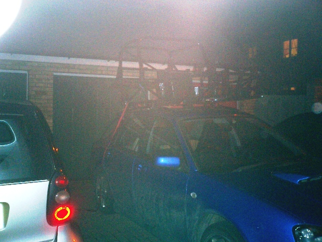
The
drive back was, erm, interesting. It was a very windy day and the roof rack bars on the Scooby are quite close
together. Still, we (the chassis and me) made in back in one piece and William very kindly helped me shift the
chassis and cage off the roof of the Scooby (it's really not a one man job) and put the engine in the engine bay.
Job done, I retired to the storage facility I've got with some friends to paint the floor.
And yes, it's a poxy photo, but it's only a likkle camera so it doesn't have a very good flash. And it seems traditional
to have a 'chassis balanced precariously on top of roof rack' photo in any self-respecting build diary.
Friday 15th December 2006
Well, work has been rather hectic once again, but I have
made some progress on the build. It seemed sensible to start off by making the engine mounts - I want the bottom
of the engine to be level with the bottom of the chassis, and the simplest way of doing this seemed to be to put
them both on the floor, line up the engine and then build the chassis mounts around it.
The steel I'm using for the engine mounts is mostly 7/8" 18 gauge CDS that Tim and Adrian used for suspension arms and
various other parts. The minimum order from the place that they get it from is quite large, so when Tim bought
the last lot I took 6m of his hands. I'm rather surprised that I don't seem to have any of it left...
The engine mounts aren't the process of an elaborate FEA-driven design study to minimise weight and increase the
stiffness of the chassis. Before I collected the chassis I'd designed lots of different elegant engine mount designs.
I'd decided that I'd like to use an engine cradle which would come out as a single unit (like in the Striker) with
the engine as far back as possible, as mentioned in the Preparation part of this site. And of course once I got
the chassis I realised that the diagonal chassis member going up to the top corner of the pedal box would made
a one-piece cradle rather tricky to get in and out of the car, so the best-laid plans of this particular man once
again went awry.
So in the end I decided just to knock something up which satisfied the following requirements:
1. Engine as far back as possible.
2. Nothing bolted through the floorpan - I want to panel the underside,
and it means you have to make access hatches or holes in the panelling. And frankly, I've never really seen why
people think it's such a good idea when it's such a PITA.
3. Use all the mounting points on the R1 engine (8 of them in total)
- just seems wrong to not use all of them, although there are plenty of designs that don't.
I
started off by getting the engine to sit where I wanted it to be. I've decided to have the engine oriented like
it is in the bike, with the bottom of the block level and the bottom of the sump sloping, so a bit of wood was
required to prop the engine up into place. A bit of measuring, a bit of engine wiggling, and everything was falling
into place.
In order to attach the mounts to the engine, rather than using the traditional Fisher method of getting a piece
of 4mm mild steel, bolting it to the engine, and then finding some way of welding some 1" box section tubing
to it, I made up some tubular mounts. They're the little bobbins you can see on the photo on the left attached
directly to the engine. They're just lengths of 1" or 1 1/4" round ERW with a bit of 2mm mild steel welded
to the bottom. Initially I MIG'd the plate in place and then turned them down on the lathe to 'dress' the weld.
However, I think I took a bit too much off and took most of the weld off, so I've gone round and TIG'd them all
now.
Then it was
just a case of working out what the closest bit of chassis was to the mounting point on the engine and cutting
a bit of steel to go between the two. Using Tim's fish-mouth cutting tool, it hasn't been too hard to get the bits
to fit reasonably closely. I've added strengthening plates to some of the joins between the tubes to give it a
bit of extra stiffness.
The last tube still has to be welded in place, a few more strengthening plates added, and all the welding finished
off. Then it's off to the powder-coaters before fitting.
Next thing to do is chassis mods. And then panelling, to get the panels ready to go off for powder-coating too.
Oooo, what fun that's going to be...
 The
drive back was, erm, interesting. It was a very windy day and the roof rack bars on the Scooby are quite close
together. Still, we (the chassis and me) made in back in one piece and William very kindly helped me shift the
chassis and cage off the roof of the Scooby (it's really not a one man job) and put the engine in the engine bay.
Job done, I retired to the storage facility I've got with some friends to paint the floor.
The
drive back was, erm, interesting. It was a very windy day and the roof rack bars on the Scooby are quite close
together. Still, we (the chassis and me) made in back in one piece and William very kindly helped me shift the
chassis and cage off the roof of the Scooby (it's really not a one man job) and put the engine in the engine bay.
Job done, I retired to the storage facility I've got with some friends to paint the floor.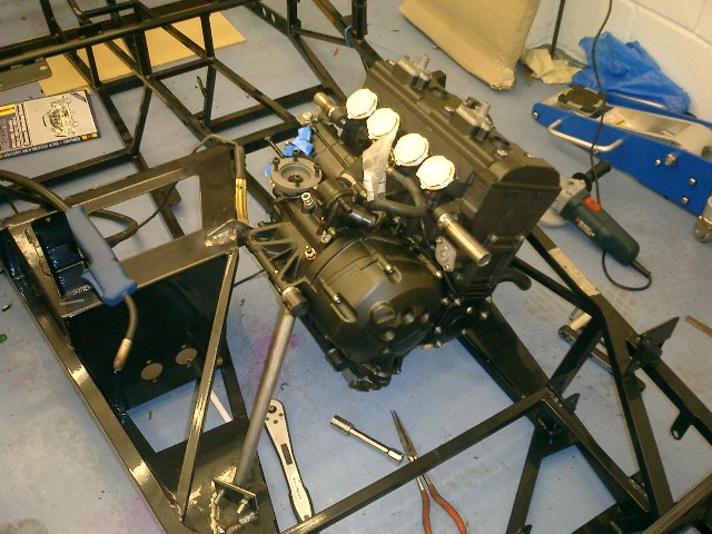
 Then it was
just a case of working out what the closest bit of chassis was to the mounting point on the engine and cutting
a bit of steel to go between the two. Using Tim's fish-mouth cutting tool, it hasn't been too hard to get the bits
to fit reasonably closely. I've added strengthening plates to some of the joins between the tubes to give it a
bit of extra stiffness.
Then it was
just a case of working out what the closest bit of chassis was to the mounting point on the engine and cutting
a bit of steel to go between the two. Using Tim's fish-mouth cutting tool, it hasn't been too hard to get the bits
to fit reasonably closely. I've added strengthening plates to some of the joins between the tubes to give it a
bit of extra stiffness.